3 Wire Liftgate Switch Wiring Diagram: Easy Setup Guide
A 3 wire liftgate switch wiring diagram illustrates the connection between the power source, the motor, and the switch. It typically features a hot wire for power, a traveler wire to send signals for movement, and a ground wire or neutral wire connection to complete the electrical circuit safely.
📌 Key Takeaways
- Main purpose is visualizing power flow from the battery to the liftgate motor.
- Identifying the common terminal is essential for ensuring the switch functions correctly.
- The ground wire must be securely fastened to prevent electrical shorts or failure.
- Always test for continuity before finalizing the physical installation of the switch.
- Use this diagram when repairing unresponsive liftgates or upgrading existing systems.
Operating a hydraulic liftgate requires a precise electrical connection to ensure the safety of both the operator and the cargo. When a switch fails or a wire corrodes, understanding a 3 wire liftgate switch wiring diagram becomes essential for a quick and effective repair. This guide provides a detailed breakdown of how the control circuit functions, identifying each terminal and wire color typically found in commercial trucking systems. By following this technical overview, you will learn how to identify the power source, signal wires, and proper grounding techniques required to restore your liftgate to full functionality.
Understanding the 3 Wire Liftgate Switch Diagram Components
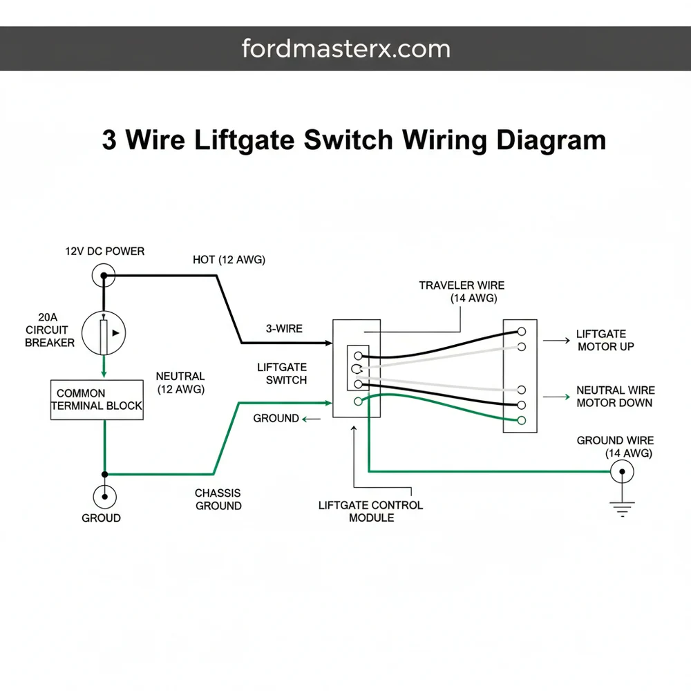
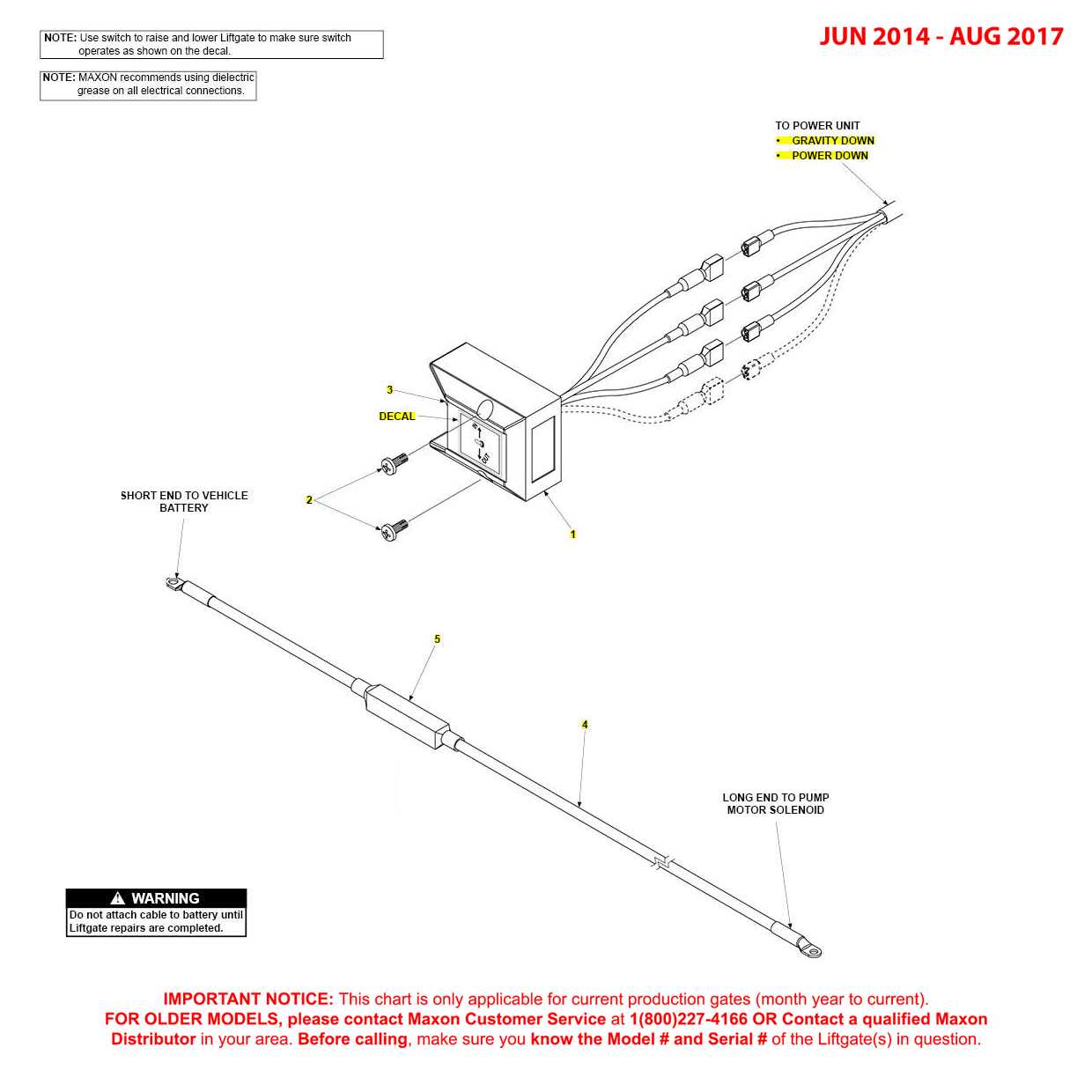
The 3 wire liftgate switch wiring diagram is the blueprint for a Single Pole Double Throw (SPDT) momentary switch. Unlike complex multi-function controllers, the 3-wire system is prized for its simplicity and durability in harsh environments. The system typically consists of three primary electrical paths: a central power feed and two directional signal paths. In most commercial applications, such as those found on Maxon or Waltco liftgates, these wires are color-coded to prevent installation errors, though colors can vary by manufacturer.
In a standard diagram, the central connection is known as the common terminal. This is where the hot wire, carrying the main 12V or 24V DC current from the battery or master disconnect, enters the switch. The remaining two terminals act as the traveler wire connections. One traveler wire sends a signal to the “up” solenoid on the hydraulic pump, while the other traveler wire sends the signal to the “down” or gravity-release solenoid.
Visually, the diagram represents the switch as a bridge. When the rocker or toggle is pressed “Up,” the internal contact connects the hot wire to the “Up” traveler. When pressed “Down,” the contact shifts to the “Down” traveler. The diagram also illustrates the relationship between the switch and the ground wire. While the switch itself may not always require a dedicated ground to function (as it merely interrupts the positive flow), the solenoids at the pump motor must have a solid connection to the chassis or a dedicated neutral wire path to complete the circuit and activate the motor.
[DIAGRAM_PLACEHOLDER: 3 Wire Liftgate Switch Wiring Diagram showing Common Terminal, Up Traveler, and Down Traveler connections with 12V Power Source and Solenoid Layout]
The physical layout of the switch often includes a brass screw for the common terminal to distinguish it from the silver-colored traveler terminals. Understanding this visual distinction is vital for preventing a “dead short” or a situation where the liftgate operates in the wrong direction. The gauge of the wire is also a critical component shown in the diagram, usually requiring 14 or 16 AWG for control circuits to handle the switch’s amperage without significant voltage drop.
Most 3-wire switches utilize a “Momentary-On” logic. This means the circuit is only closed while you are physically pressing the button. Releasing the button immediately breaks the connection to the traveler wire, stopping the liftgate’s movement.
Step-by-Step Installation and Wiring Guide
Following a 3 wire liftgate switch wiring diagram requires a methodical approach to ensure the electrical integrity of the vehicle. Before beginning, ensure you have the correct tools, including a wire stripper, crimping tool, heat-shrink tubing, and a digital multimeter to verify voltage levels.
- ✓ Step 1: Power Disconnection and Safety – Always begin by disconnecting the main power source from the liftgate motor. Locate the master fuse or disconnect the positive cable from the battery. This prevents accidental shorting if a traveler wire touches the vehicle chassis during the installation process.
- ✓ Step 2: Identify the Hot Wire – Use your multimeter to identify the live wire coming from the power source. With the battery reconnected briefly for testing, this wire should show a steady 12V or 24V reading. Once identified, label this as your “Hot” or “Common” lead.
- ✓ Step 3: Locate the Common Terminal – Look at the back of your replacement switch. The common terminal is usually located in the center or is marked with a brass screw. Connect your identified hot wire to this terminal. Ensure the connection is tight and free of stray wire strands.
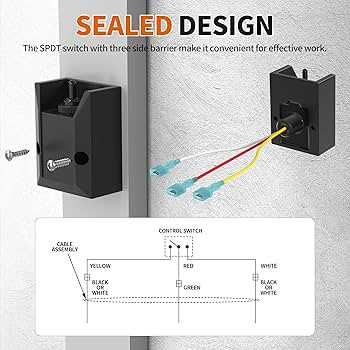
- ✓ Step 4: Connect the Up Traveler Wire – Identify the wire leading to the “Raise” or “Up” solenoid. In many systems, this is the white or green wire. Attach this to the top terminal of the switch. If you are using a toggle switch, remember that the internal contact moves opposite to the handle; consult your diagram to ensure “Up” on the handle correlates with the “Up” solenoid.
- ✓ Step 5: Connect the Down Traveler Wire – Attach the remaining wire (often black or red, depending on the manufacturer) to the “Down” terminal. This wire triggers the solenoid that allows hydraulic fluid to return to the reservoir, lowering the gate via gravity or power-down pressure.
- ✓ Step 6: Secure the Ground Wire – While the switch itself may not have a ground terminal, the liftgate housing must be properly grounded. Check the ground wire connection from the pump to the vehicle frame. A poor ground is the leading cause of “switch failure” when the switch itself is actually functional.
- ✓ Step 7: Weatherproofing and Testing – Apply dielectric grease to the terminals to prevent corrosion. Slide heat-shrink tubing over the connections and seal them. Reconnect the power and test the movement. Ensure that “Up” raises the gate and “Down” lowers it.
Never substitute a standard light switch for a liftgate switch. Standard switches are often rated for AC voltage and lack the “Momentary” spring-back action. Using the wrong switch type can cause the liftgate to move uncontrollably or burn out the hydraulic motor.
Common Issues & Troubleshooting
Even with a perfect 3 wire liftgate switch wiring diagram, environmental factors can cause system failures. The most common issue is a “clicking” sound coming from the pump motor without any movement. This usually indicates that the switch is successfully sending a signal through the traveler wire, but there is insufficient voltage to activate the solenoid. This can be caused by a corroded brass screw on the switch terminal or a frayed hot wire that is barely making contact.
Another frequent problem is reversed operation. If the gate goes down when you press up, the traveler wires are swapped. Simply switch the positions of the two outer wires on the terminals to rectify this. If the liftgate does not move at all, use a jumper wire to briefly touch the common terminal to one of the traveler terminals. If the gate moves, the switch is defective. If it still doesn’t move, the problem likely lies in the ground wire or the motor solenoids rather than the switch itself.
If you are stuck on the road and the switch fails, you can often manually bypass it by identifying the hot wire and the traveler wire for the “Up” function and touching them together directly. This should only be done in emergencies to stow the gate for travel.
Tips & Best Practices for Maintenance
Maintaining your liftgate’s electrical system involves more than just fixing broken wires. To ensure longevity, always use the correct wire gauge for your control circuit. While the solenoids don’t pull massive amperage, a gauge that is too thin (higher number) will result in a voltage drop that can cause solenoids to chatter and eventually weld themselves shut. Stick to 14 or 16 AWG multi-strand copper wire for the best balance of flexibility and conductivity.
Regularly inspect the entry point where the 3-wire harness enters the switch box. This is a common failure point where vibrations can rub the insulation off the hot wire, leading to blown fuses or intermittent operation. Using a protective loom or “snake skin” over the wires can prevent this abrasion. Additionally, avoid using electrical tape as a permanent sealant; it eventually loses its adhesive properties in extreme heat or cold. Heat-shrink connectors are the industry standard for a reason—they provide a mechanical bond and a moisture-proof seal.
For cost-saving, consider purchasing high-quality sealed switches. While a generic 3-wire toggle might be cheaper, a marine-grade or heavy-duty industrial switch is designed to withstand the salt, rain, and road debris that liftgates encounter daily. Investing in a switch with an IP67 rating will save you significant money in the long run by reducing the frequency of replacements and the downtime associated with electrical failures.
By adhering to the specifications found in a 3 wire liftgate switch wiring diagram and maintaining clean, tight connections, you ensure that your equipment remains a reliable asset for your logistics operations. Proper terminal identification and wire management are the foundations of a safe and efficient hydraulic lift system.
Frequently Asked Questions
Where is the liftgate switch located?
The switch is usually found on the rear exterior pillar, inside the cargo area, or integrated into the rear handle assembly. It acts as the user interface to trigger the liftgate’s motor or actuator for opening and closing the rear hatch.
What does this wiring diagram show?
The 3 wire liftgate switch wiring diagram maps the flow of electricity through the hot wire, the traveler wire, and the ground wire. It shows how the switch interacts with the relay or control module to activate the liftgate’s mechanical movement.
How many connections does a liftgate switch have?
A standard 3-wire setup includes three primary connections: a power lead (hot wire), a ground or neutral wire, and a traveler wire. The traveler wire links the switch directly to the actuator or the vehicle’s central control module.
What are the symptoms of a bad liftgate switch?
Common signs of failure include the liftgate not responding to button presses, intermittent operation where it works only occasionally, or the liftgate moving in only one direction despite the wiring being intact and receiving power from the battery.
Can I replace this switch myself?
Yes, with basic hand tools and a clear 3 wire liftgate switch wiring diagram, most DIYers can safely replace the switch. It involves disconnecting the battery, removing the old switch, and matching the wires to the new component accurately.
What tools do I need for this task?
You will need a digital multimeter for testing voltage and continuity, wire strippers for prepping connections, a screwdriver set for panel removal, and high-quality crimp connectors or electrical tape to ensure a secure and insulated finish.