2005 Ford F150 Starter Wiring Diagram: Easy Setup Guide
The 2005 Ford F150 starter wiring diagram illustrates how the hot wire delivers battery power to the solenoid’s common terminal. When the ignition is turned, a traveler wire provides the signal to engage. Ensure the ground wire is clean and the neutral wire circuit through the safety switch is functional.
📌 Key Takeaways
- Visualizes the high-current path from the battery to the starter motor
- The starter solenoid is the critical junction for all electrical signals
- Always disconnect the battery negative cable before touching starter wires
- Corroded terminals are the most common cause of voltage drop and failure
- Use this diagram when the engine clicks or fails to crank during ignition
Troubleshooting the ignition system on a high-mileage pickup can be a daunting task without a clear roadmap. If you are struggling with a truck that refuses to crank or only provides a faint clicking sound, understanding the 2005 Ford F150 starter wiring diagram is your first step toward a successful DIY repair. This article provides a comprehensive breakdown of the electrical pathways between your battery, the ignition switch, and the starter motor itself. By learning how these components interact, you will be able to identify faulty connections, test for appropriate voltage, and replace components with the confidence of a professional mechanic. We will explore color codes, terminal locations, and the specific sequence required to energize the motor.
The electrical architecture of the 2005 Ford F150 starting system is designed for high-current delivery and safety-interlocked logic. At the heart of the system is the starter solenoid, which acts as a heavy-duty relay. In the 2005 Ford F150 starter wiring diagram, you will observe three primary connection points on the solenoid housing. The first is the B-terminal (Battery), which is the common terminal where the large-gauge hot wire from the battery positive post connects. This wire is typically a thick, red 4-gauge or 2-gauge cable designed to handle the massive amperage required to turn the engine over.
The second connection is the S-terminal (Start), which receives the trigger signal. This wire is significantly smaller in gauge and is often colored yellow with a light blue stripe. In residential wiring, you might think of this as a traveler wire because it carries the signal from the ignition relay down to the starter to “tell” it to engage. When you turn your key to the “Start” position, 12 volts travel through this wire to the solenoid.
The third component is the M-terminal (Motor), which is an internal connection or a short braided lead that carries power from the solenoid body into the starter motor brushes. Unlike a household circuit that requires a dedicated white neutral wire to return current to the source, the 2005 Ford F150 relies on the engine block and a heavy-duty ground wire for its return path. The starter housing is bolted directly to the transmission bellhousing, creating a ground connection. If the brass screw or mounting flange of the starter is corroded, the circuit will fail despite having a perfect hot wire connection.
The 2005 Ford F150 uses a “Permanent Magnet Gear Reduction” (PMGR) starter. This design allows for a smaller, lighter motor that produces high torque, but it is highly sensitive to voltage drops caused by corroded or loose wiring connections.
To properly use the 2005 Ford F150 starter wiring diagram for a repair or installation, follow these detailed steps to ensure the circuit is completed correctly and safely.
- ✓ Step 1: Preparation and Safety – Before touching any wiring, park the vehicle on a level surface and engage the parking brake. Disconnect the negative battery cable (the ground wire) from the battery. This is vital because the main hot wire at the starter is “always live” and carries enough current to cause a fire or severe injury if it accidentally touches the frame while you are working with a wrench.
- ✓ Step 2: Locate the Starter Motor – On the 2005 F150, the starter is located on the passenger side of the engine, tucked between the block and the frame rail, near the rear of the oil pan. You will see two or three wires leading to the solenoid mounted on top of the starter motor.
- ✓ Step 3: Connect the Main Power (B-Terminal) – Identify the thickest cable in the harness. This is your primary hot wire coming directly from the battery or the battery junction box. Slide the ring terminal over the largest threaded post (the common terminal) on the solenoid. In many aftermarket units, this post may be secured with a brass screw or a large nut. Ensure the connection is tight but do not over-torque, as the solenoid cap is made of plastic and can crack.
- ✓ Step 4: Attach the Ignition Signal (S-Terminal) – Look for the thinner wire, usually yellow/light blue. This is the signal wire that carries the voltage when the ignition is turned. It typically uses a smaller nut or a push-on spade connector. Refer to your 2005 Ford F150 starter wiring diagram to ensure you aren’t confusing this with a ground, as this wire must only be energized when the key is in the start position.
- ✓ Step 5: Verify the Ground Path – Unlike residential systems that utilize a neutral wire, the F150 starter is grounded through its chassis. Ensure the mounting surface on the engine block is clean. If you are experiencing “slow cranking,” consider adding an auxiliary ground wire from one of the starter mounting bolts directly to the vehicle frame.
- ✓ Step 6: Check the Neutral Safety Switch – The circuit is not complete without the Digital Transmission Range (TR) sensor. This sensor ensures the truck only starts in Park or Neutral. If your diagram shows power reaching the relay but not the starter, the TR sensor or its wiring may be the culprit.
- ✓ Step 7: Final Testing – Reconnect the battery ground wire. Use a multimeter to check the voltage at the battery (should be 12.6V). Have an assistant turn the key while you measure the voltage at the S-terminal. If you see 12V there but the starter doesn’t move, the internal solenoid contacts are likely burned.
Never attempt to “jump” the starter terminals with a screwdriver unless you are experienced. The high amperage can cause an immediate arc flash, potentially welding the tool to the frame or causing the battery to explode if there is a short circuit.
When troubleshooting the 2005 Ford F150, several common issues frequently appear. The most prevalent is the “single click” symptom. This usually indicates that the solenoid is receiving voltage from the traveler wire and is trying to engage, but the main common terminal is not delivering enough current to turn the motor. This is often caused by a corroded hot wire or a weak battery.
Another issue involves the starter staying engaged after the engine has started. This often points to a sticking ignition relay in the battery junction box or a short circuit in the signal wiring. If the wire gauge of a replacement cable is too thin, it may overheat and fail, causing an intermittent “no-start” condition when the engine is hot. Use your wiring diagram to trace the path from the fuse box to the solenoid to ensure no wires have melted against the exhaust manifold, which is a common hazard on the 5.4L and 4.6L Triton engines.
Before replacing a starter, always perform a “Voltage Drop Test.” Set your multimeter to DC volts and place one lead on the battery positive and the other on the starter’s B-terminal while cranking. If you see more than 0.5V, your cable or connections are the problem, not the starter itself.
To maintain the longevity of your 2005 Ford F150 starter and its wiring, follow these best practices. First, always ensure your battery terminals are free of the white, powdery corrosion that plagues Ford trucks of this era. Use a wire brush to clean the brass screw terminals and the lead battery posts. Applying a thin layer of dielectric grease can prevent moisture from entering the connections and causing resistance.
When buying replacement parts, prioritize high-quality OEM or reputable aftermarket units. Cheap starters often use inferior copper windings and thinner gauge internal wiring, leading to premature failure in cold weather. Furthermore, ensure that the heat shield originally installed on your F150 is transferred to the new starter. The heat from the exhaust manifold can quickly degrade the insulation on the hot wire and signal wire, leading to a “dead” spot in the motor.
Finally, keep an eye on your alternator’s health. A weak alternator forces the battery to work harder, which in turn provides lower voltage to the starter. Over time, low voltage increases the amperage draw, which generates excessive heat and wears out the solenoid contacts faster. By following the 2005 Ford F150 starter wiring diagram and maintaining clean, tight connections, you can ensure your truck starts reliably every time you turn the key. Whether you are dealing with a faulty ground wire or a complicated signal issue, a methodical approach based on the correct diagram is the best way to get back on the road.
Step-by-Step Guide to Understanding the 2005 Ford F150 Starter Wiring Diagram: Easy Setup Guide
Identify the battery and disconnect the negative terminal to prevent electrical shorts.
Locate the starter motor assembly on the lower passenger side of the engine block.
Understand how the traveler wire carries the trigger signal from the ignition switch.
Connect the heavy-duty hot wire to the solenoid common terminal and tighten the nut.
Verify that the ground wire connection between the battery and the frame is clean.
Complete the installation by securing the mounting bolts and testing the ignition crank.
Frequently Asked Questions
Where is the 2005 Ford F150 starter located?
The starter on a 2005 Ford F150 is located on the lower passenger side of the engine, bolted to the transmission bellhousing. It is best accessed by crawling under the vehicle and looking near the oil pan area. Ensure the vehicle is properly supported on jack stands.
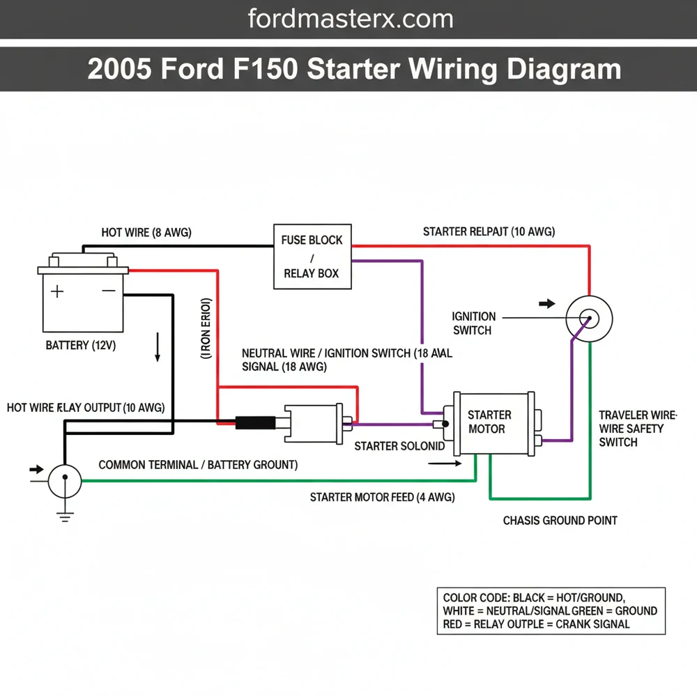
What does the 2005 Ford F150 starter wiring diagram show?
This diagram illustrates the electrical flow from the battery to the starter motor. It highlights the main hot wire, the ignition trigger traveler wire, and the ground wire connections. It helps users trace faults in the starting circuit, including the relay and neutral safety switch components.
How many wires does the 2005 Ford F150 starter have?
The 2005 Ford F150 starter typically features two main electrical connections on the solenoid. The large common terminal receives the heavy-gauge hot wire directly from the battery. A smaller S-terminal connects to the signal wire from the ignition switch, while the unit is grounded through its mounting.
What are the symptoms of a bad 2005 Ford F150 starter?
Common symptoms of a failing starter include a single loud click when turning the key or a rapid clicking sound. You might also experience intermittent starting, where the engine only cranks after several attempts. Smoke coming from the starter or a grinding noise are also signs of failure.
Can I replace the F150 starter myself?
Replacing the starter is a common DIY task that takes about an hour. You must disconnect the battery first to avoid shorting the hot wire. Once the electrical leads are removed, unbolting the unit is straightforward. Most owners with basic mechanical skills can complete this repair successfully.
What tools do I need for F150 starter replacement?
To work on the starter, you will need a 10mm and 13mm socket set with extensions to reach the mounting bolts. A wire brush is essential for cleaning the common terminal and ground wire points. A multimeter is also recommended to test for voltage at the traveler wire.


