2004 Ford F150 Fuse Box Diagram: Quick Identification Guide
The 2004 Ford F150 fuse box diagram identifies the central junction box located behind the kick panel on the passenger side. It maps out circuits for the fuel pump, ECU, and interior lights. Using this layout allows you to quickly locate blown fuses, diagnose issues, and restore power to critical vehicle systems.
📌 Key Takeaways
- Identifies the location of every fuse and relay in the vehicle
- Helps pinpoint the specific fuse for the ECU and fuel system
- Essential for preventing electrical fires during DIY repairs
- Saves time when troubleshooting dead interior components or lights
- Use this diagram whenever the radio, wipers, or windows fail
Locating a reliable 2004 ford f150 fuse box diagram is the first step toward reclaiming control over your vehicle’s electrical system. Whether you are dealing with a dead radio, a malfunctioning interior light, or a more serious issue like a no-start condition, the fuse box serves as the central nervous system for your truck’s power distribution. Understanding how to navigate this panel is essential for any DIY enthusiast, as it allows you to identify blown circuits without expensive trips to the dealership. This guide provides a detailed breakdown of the internal and external fuse locations, ensuring you have the technical knowledge to troubleshoot common electrical faults effectively.
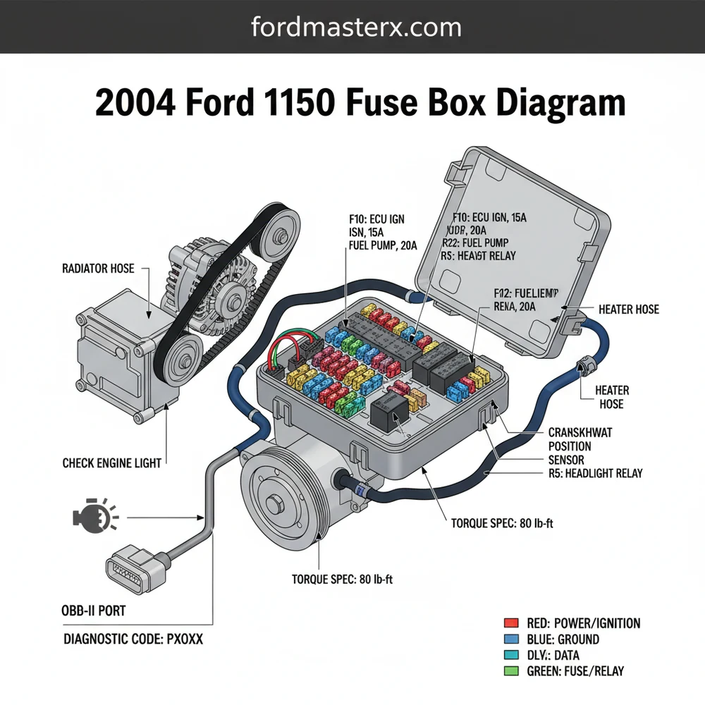
The 2004 Ford F-150 features two primary electrical centers: the Central Junction Box (CJB) located behind the passenger-side kick panel and the Battery Junction Box (BJB) located under the hood near the battery. Most consumer-facing issues, like the OBD-II port power, are found in the CJB.
Deep Dive into the 2004 Ford F150 Fuse Box Diagram
The primary 2004 ford f150 fuse box diagram covers the Central Junction Box, which contains 48 individual fuse slots and several larger relays. This panel is organized in a grid format, where each number corresponds to a specific amperage and automotive system. For instance, the fuses are color-coded according to industry standards: Tan for 5A, Red for 10A, Blue for 15A, and Yellow for 20A. Understanding this color scheme is vital when you are leaning into the cramped footwell of your truck, as it provides a quick visual reference before you even pull a fuse.
The diagram identifies critical components like the ECU (Engine Control Unit) power supply, the instrument cluster, and the fuel pump relay. A common point of confusion for 2004 owners is the distinction between the “Heritage” model and the “New Body Style.” This guide focuses on the New Body Style, which was the primary production run for 2004. In this layout, Fuse 41 is a frequent culprit for issues, as it powers both the cigarette lighter and the OBD-II diagnostic port. If your scan tool won’t power up to read a diagnostic code, this is the first place to look.
| [31] | [21] | [11] | [01] |
| [32] | [22] | [12] | [02] |
| [33] | [23] | [13] | [03] |
| [34] | [24] | [14] | [04] |
| [35] | [25] | [15] | [05] |
| [36] | [26] | [16] | [06] |
| [37] | [27] | [17] | [07] |
| [38] | [28] | [18] | [08] |
| [39] | [29] | [19] | [09] |
| [40] | [30] | [20] | [10] |
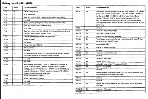
The under-hood Battery Junction Box (BJB) handles higher current loads. This is where you will find the “Maxi” fuses and relays for heavy-duty components. These include the cooling fan relays, which are crucial for maintaining proper coolant flow through the radiator, and the starter solenoid relay. If your truck is overheating or failing to crank, the BJB diagram is your roadmap for testing.
Step-by-Step Guide: Interpreting and Replacing Fuses
Effectively using the 2004 ford f150 fuse box diagram requires a methodical approach. Electrical systems are sensitive, and improper handling can lead to short circuits or damage to the sensitive ECU. Follow these steps to safely diagnose and resolve fuse-related issues.
- Locate the Panel: The passenger kick panel is the most common site for troubleshooting. To access it, open the passenger door, pull the plastic trim panel toward the center of the cab, and remove the cover. You will see the fuse layout printed on the inside of the cover, though it is often difficult to read without a flashlight.
- Identify the Circuit: Refer to your 2004 ford f150 fuse box diagram to match the malfunctioning component (e.g., “Windows”) to a fuse number. For example, Fuse 40 (20A) often controls the fuel pump circuitry. Knowing the exact number prevents you from pulling every fuse and potentially resetting the truck’s computer.
- Inspect the Fuse: Use a plastic fuse puller tool (usually found in the BJB or purchased at an auto parts store). Pull the fuse straight out. Look at the metal filament inside the translucent plastic. If the “U” shaped wire is broken or if there is a dark burn mark, the fuse is blown.
- Test with a Multimeter: For a more accurate reading, set a multimeter to the “Continuity” or “Ohms” setting. Touch the probes to the two small metal tabs on the top of the fuse while it is still installed. A beep or a “0.00” reading indicates the fuse is good. No beep indicates an open circuit.
- Check for Power: If the fuse is good but the component isn’t working, use a test light to ensure power is reaching the fuse slot. With the ignition in the “ON” position, touch the test light to both sides of the fuse. If only one side lights up, the fuse is blown. If neither side lights up, the problem lies further up the line toward the battery or ignition switch.
- Install the Correct Replacement: Never replace a blown fuse with one of a higher amperage. If the diagram calls for a 15A blue fuse, do not use a 20A yellow fuse. Doing so can cause the wiring to overheat before the fuse blows, potentially leading to a vehicle fire.
- Verify the Repair: Turn the ignition on and test the component. If the fuse blows again immediately, you have a short circuit in that specific wiring harness that needs further investigation.
Always turn off the ignition and remove the key before pulling fuses. Some circuits are “always hot,” meaning they have live current even when the truck is off. Removing these without care can cause a small spark that might trigger a check engine light or a diagnostic code.
Common Issues & Troubleshooting
The 2004 F-150 is known for a few specific electrical quirks that are easily solved by consulting the fuse box diagram. One of the most frequent complaints is the loss of the OBD-II port communication. When you take your truck for an emissions test and the technician says their computer “can’t talk” to your ECU, it is almost always Fuse 41. This fuse also powers the cigarette lighter; if you’ve dropped a coin in the lighter socket, it will pop this fuse, disabling your diagnostic capabilities.
Another common issue involves the check engine light. While the light itself is triggered by the ECU, the sensors it monitors (like O2 sensors) often have dedicated fuses. If multiple sensor codes appear simultaneously, check the fuse box for a single blown fuse that supplies power to the entire sensor bank. Furthermore, if you experience a “crank but no start” condition, check the fuel pump relay (Relay R02) and its associated fuse. A faulty relay can mimic the symptoms of a failed fuel pump, but a relay replacement is significantly cheaper and easier.
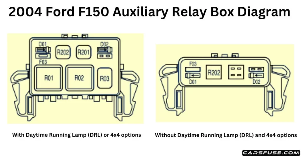
If you are experiencing intermittent power loss to the radio or windows, check the Accessory Delay Relay (Relay R05). This relay keeps power to these components until you open the door. Over time, the solder joints in this relay can crack, causing frustrating intermittent failures.
Tips & Best Practices for Maintenance
Maintaining the electrical health of your 2004 F-150 goes beyond just swapping fuses. While you are under the hood checking the BJB, take a moment to inspect your battery terminals. Ensure they are tightened to the correct torque spec (usually around 10-15 lb-ft for the terminal clamps) to prevent voltage drops. High resistance at the battery can cause various “ghost” electrical issues that might lead you to believe a fuse is blown when the system is actually just under-powered.
- ✓ Keep Spare Fuses: Always keep a variety pack of Mini and Maxi fuses in your glove box.
- ✓ Clean the Box: If you live in a humid climate, check for corrosion on the fuse blades. A small amount of dielectric grease can prevent moisture from causing high resistance.
- ✓ Check Mechanical Links: Remember that some “electrical” failures are mechanical. If your cooling fans won’t turn on, it could be a fuse, but it could also be a blockage in the coolant flow or a worn accessory belt failing to drive the water pump correctly.
- ✓ Listen for Relays: A good relay should make a faint “click” when activated. If you suspect a relay is bad, swap it with a known good one of the same part number (e.g., swapping the horn relay for the fuel pump relay) for testing purposes.
Finally, be aware that while the 2004 Ford F-150 is a robust truck, its 5.4L 3V engine models are sensitive to voltage. A failing alternator can cause the ECU to throw a false diagnostic code related to the timing chain phasers or ignition coils. Always ensure your charging system is providing a steady 13.5 to 14.5 volts before assuming an electrical component has failed. By mastering the 2004 ford f150 fuse box diagram, you equip yourself with the primary tool needed to keep your truck on the road and out of the shop. This knowledge saves time, reduces frustration, and ensures that you can handle both minor inconveniences and major diagnostic hurdles with confidence.
Frequently Asked Questions
Where is the fuse box located?
The main passenger compartment fuse box is behind a plastic cover on the passenger side kick panel. There is also a battery junction box under the hood. Knowing these spots is vital for accessing the ECU and other modules when performing routine maintenance or electrical repairs on your truck.
What does the fuse box diagram show?
This diagram displays the location, amperage rating, and specific circuit for every fuse and relay. It maps out critical paths for the OBD-II port, engine sensors, and cabin electronics. This visualization is the primary tool for diagnosing phantom electrical drains or sudden circuit failures in your Ford truck.
How many connections does a standard relay have?
Most relays in this vehicle feature four or five pins, while fuses use two-prong blade-style connectors. Each slot connects specific components like the fuel pump to the battery. Proper contact ensures the OBD-II system can communicate with the engine computer without interruption or unexpected voltage drops during operation.
What are the symptoms of a bad fuse?
A bad fuse usually results in a specific component failing, while a relay might cause intermittent power loss. If your check engine light is on, a blown fuse might prevent a handheld scanner from pulling a diagnostic code. A visual inspection usually reveals a broken or burnt metal filament.
Can I replace the fuses myself?
Replacing a fuse or relay is a simple DIY task that requires no special tools. Most owners can swap these parts in minutes to resolve lighting or starting issues. However, if a fuse blows repeatedly, you must investigate the underlying short circuit to prevent permanent electrical damage or fire.
What tools do I need for fuse replacement?
You primarily need a fuse puller tool, which is often located inside the fuse box cover. A multimeter is also helpful for testing continuity. If you are removing ground wires or battery terminals, ensure you follow the manufacturer’s torque spec to maintain a secure and safe electrical connection.


