2004 F350 Fuse Box Diagram: Quick Identification Guide
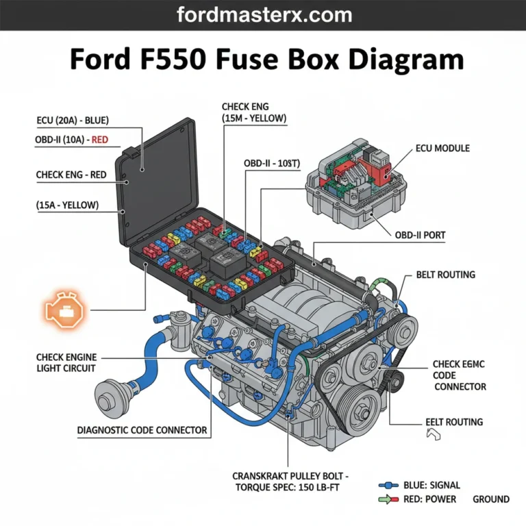
The 2004 F350 fuse box diagram labels the passenger compartment panel located under the steering column and the power distribution box found in the engine bay. These diagrams identify circuit ratings for components like the ECU and lighting, facilitating rapid troubleshooting when you encounter electrical failures or a check engine light.
📌 Key Takeaways
- The diagram identifies locations for both internal and external fuse panels.
- Fuses for the ECU and fuel pump are critical for engine operation.
- Always match the amperage rating exactly to avoid electrical fires.
- Use the diagram to troubleshoot power loss before replacing expensive sensors.
- Keep a printed copy in the glovebox for emergency roadside repairs.
The 2004 Ford F-350 Super Duty is a workhorse known for its reliability, but like any vehicle that has been on the road for two decades, electrical issues are bound to arise. Whether you are dealing with a dead radio, malfunctioning trailer lights, or a truck that simply won’t start, the fuse box is the first place every DIY enthusiast should look. Understanding the 2004 F-350 fuse box diagram is not just about finding a blown fuse; it’s about understanding the nervous system of your truck. This guide provides a comprehensive breakdown of the fuse panels, their locations, and how to navigate them to get your Super Duty back in peak operating condition.
Main Components and Fuse Box Locations
The 2004 Ford F-350 features two primary fuse boxes that manage the vehicle’s electrical distribution. For a DIYer, knowing where these are located and what they look like is half the battle. Accessing these panels doesn’t require heavy machinery, but a flat-head screwdriver or a trim removal tool can be helpful for the interior panel.
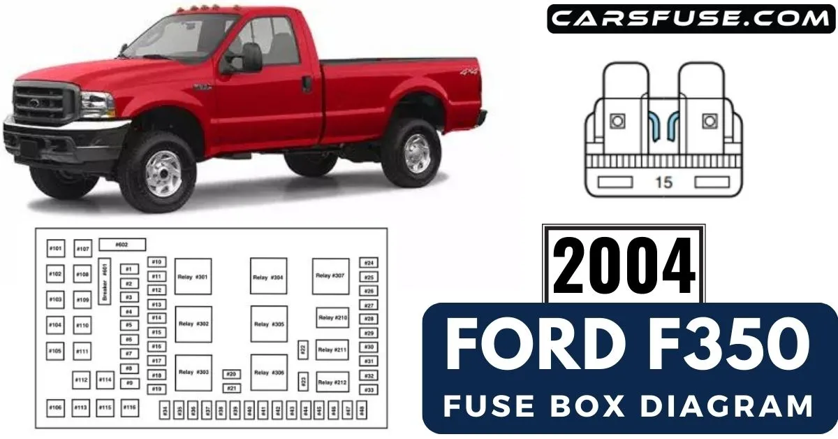
1. The Passenger Compartment Fuse Panel (Central Junction Box): This is the most frequently accessed fuse box. It is located under the steering column, behind the knee bolster. To access it, you need to turn the two plastic fasteners on the cover and pull the panel down. Once removed, you will see a grid of mini-fuses and several larger relays. This panel controls most of the cabin electronics, including the instrument cluster, power windows, and interior lighting.
2. The Engine Compartment Fuse Panel (Battery Junction Box): This box is located under the hood, typically on the driver’s side near the brake master cylinder and the firewall. It is a black, rectangular plastic box with a snap-on lid. This panel houses high-current “Maxi” fuses and relays that control heavy-duty systems like the fuel pump, ABS, trailer tow power, and the cooling fans. Because these fuses handle higher amperage, they are physically larger than the ones found inside the cab.
How to Read and Use the Fuse Box Diagram

Reading a fuse box diagram can feel like deciphering a secret code if you aren’t familiar with the terminology. Each fuse is assigned a number (e.g., Fuse 11) and an amperage rating (e.g., 10A). The amperage rating is critical; it represents the maximum current the fuse can handle before the internal wire melts to protect the circuit.
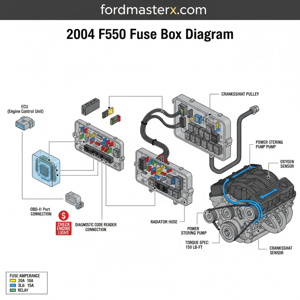
When looking at the 2004 F-350 diagram, you will notice a color-coding system used for the mini-fuses in the cab:
- Red: 10 Amps
- Blue: 15 Amps
- Yellow: 20 Amps
- Clear/White: 25 Amps
- Green: 30 Amps
To use the diagram effectively, match the number stamped on the plastic housing of the fuse box to the corresponding number in your owner’s manual or a digital diagram. For example, in the passenger compartment panel:
| Fuse Number | Amperage | Protected Component |
|---|---|---|
| 1 | 15A | Adjustable Pedals, Power Mirrors |
| 11 | 10A | Instrument Cluster, Transmission Overdrive Switch |
| 18 | 10A | Brake-Shift Interlock, PCM Relay Coil |
| 27 | 15A | Ignition Coil (Gas), Fuel Heater (Diesel) |
| 45 | 10A | Auxiliary Power, Upfitter Switches (if equipped) |
In the engine compartment (Battery Junction Box), you will find larger Maxi-fuses. Common ones to check include Fuse 101 (30A) for the Trailer Tow ST/Turn lights and Fuse 113 (30A) for the Starter Solenoid. If your truck won’t turn over but the battery is good, Fuse 113 is your primary suspect.
Essential Maintenance Tips for F-350 Owners
Working with the electrical system of a heavy-duty truck requires a few specific tools and habits. For the DIY enthusiast, having a “fusing kit” in your glove box is highly recommended. This should include a variety of mini and maxi fuses, a fuse puller tool (usually found inside the fuse box cover), and a digital multimeter.
Visual Inspection: You don’t always have to pull a fuse to see if it’s blown. Most modern fuses have a clear plastic top. If the “U” shaped wire inside is broken or if there is a dark brown scorch mark, the fuse is blown. However, some fuses can have hairline fractures that are invisible to the naked eye, which is where a multimeter comes in.
Testing with a Multimeter: Set your multimeter to the Continuity setting (the one that beeps). Touch the probes to the two small metal tabs on the top of the fuse while it is still plugged into the box. If it beeps, the fuse is good. If there is silence, the circuit is broken.
Troubleshooting Common 2004 F-350 Electrical Issues
Because the 2004 F-350 is frequently used for towing and heavy labor, certain electrical circuits are more prone to failure than others. Here are the most common troubleshooting scenarios:
1. Trailer Lights Not Working
If your truck’s lights work but your trailer’s lights are dark, check the Engine Compartment Fuse Box. The 2004 model uses separate fuses for the trailer circuits to prevent a trailer short from killing the truck’s main lights. Check Fuse 38 (20A) in the cab and Fuses 101 and 107 under the hood. Also, check the trailer tow relays; they are notorious for corroding if the truck is used in salty or wet environments.
2. Power Windows or Radio Cut Out
If multiple accessories fail at once, it is rarely a fuse issue and often a “Delayed Accessory Relay” issue. This relay keeps the power on for a few minutes after you turn off the key. In the 2004 F-350, this is often located in the Passenger Compartment Fuse Panel. If Fuse 3 (10A) and Fuse 4 (10A) are intact, the relay itself may need replacement.
3. No Crank / No Start
For diesel owners with the 6.0L engine, a common culprit for a no-start condition is Fuse 22 (10A) in the engine compartment, which controls the Fuel Injection Control Module (FICM) logic. If this fuse is blown, the engine will crank but will not fire. For gas engines, check Fuse 113 (30A) in the engine bay and the starter relay. Wire colors for the starter circuit are typically Dark Blue and Orange.
4. 4WD Not Engaging
The 2004 F-350 uses an Electronic Shift-on-the-Fly (ESOF) system. If your dash light doesn’t come on and the transfer case won’t shift, check Fuse 19 (10A) and Fuse 27 (15A) in the cab. These provide the signal to the 4×4 control module. If the fuses are good, the vacuum hubs or the transfer case motor are likely the cause, but the fuse check saves you hours of mechanical labor.
Conclusion
The 2004 Ford F-350 is a robust machine, but its electrical system requires occasional attention. By keeping a copy of the fuse box diagram handy and understanding the distinction between the interior and engine bay panels, you can solve the majority of electrical gremlins yourself. Always remember to start with the simplest solution—the fuse—before moving on to expensive components like sensors or wiring harnesses. With the right tools and a bit of patience, maintaining the electrical integrity of your Super Duty is a manageable and rewarding DIY task.
Step-by-Step Guide to Understanding the 2004 F350 Fuse Box Diagram: Quick Identification Guide
Identify – Start by identifying which electrical component has failed to narrow down which fuse panel to inspect.
Locate – Locate the 2004 F350 fuse box diagram on the inside of the fuse panel cover or in the manual.
Understand – Understand the circuit mapping to find the specific fuse number associated with the malfunctioning component or check engine light.
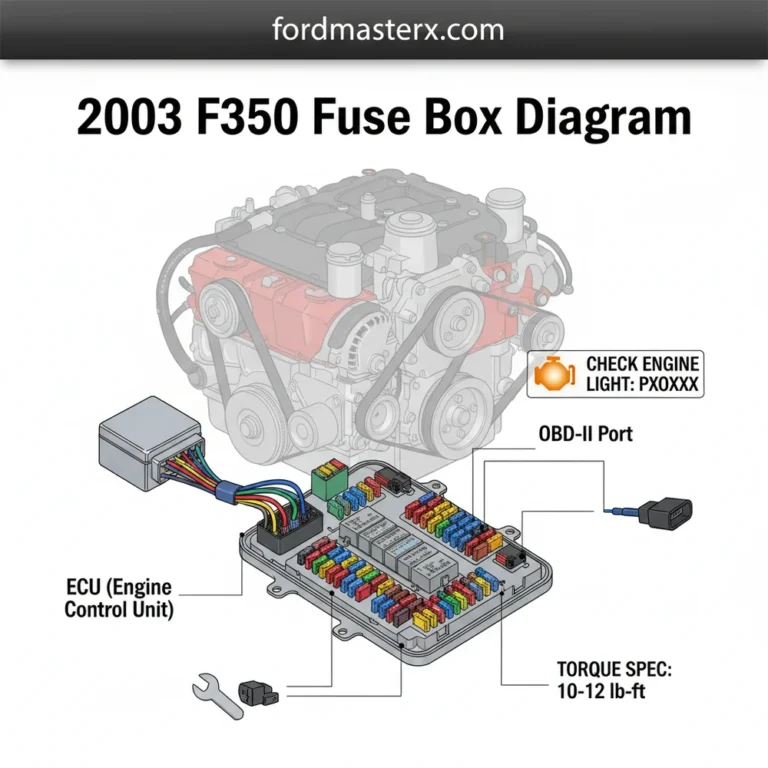
Connect – Connect a diagnostic scanner to the OBD-II port if you need to retrieve a specific diagnostic code before pulling fuses.
Verify – Verify the condition of the fuse by pulling it out and checking for a broken internal filament or burn marks.
Complete – Complete the repair by inserting a new fuse of the correct amperage and checking the mounting bolt torque spec if necessary.
Frequently Asked Questions
Where is the 2004 F350 fuse box located?
The 2004 F350 features two main fuse locations. The passenger compartment fuse panel is positioned under the dashboard to the left of the steering column behind a removable cover. The high-current power distribution box is located under the hood on the driver’s side, near the firewall and brake master cylinder.
What does the 2004 F350 fuse box diagram show?
The diagram provides a visual map of all fuses, relays, and diodes within the vehicle’s electrical system. It specifies the numerical position of each fuse, the corresponding amperage rating, and the specific circuit it protects, such as the radio, power windows, headlights, or the engine control module.
How many connections does the OBD-II circuit have?
The OBD-II system uses a standard 16-pin connector to interface with the vehicle’s computer. In a 2004 F350, the OBD-II diagnostic port typically shares a fuse with the cigarette lighter or auxiliary power point, so if your scanner won’t power up, check that specific fuse first.
What are the symptoms of a bad fuse in an F350?
Common symptoms include sudden loss of power to specific accessories like the blower motor or power seats. If a critical fuse for the ECU blows, you may experience a no-start condition or a check engine light. Always check for a broken metal bridge inside the transparent fuse casing.
Can I replace the 2004 F350 fuses myself?
Yes, fuse replacement is a basic DIY task that requires no mechanical experience. By following the 2004 F350 fuse box diagram, you can identify and swap a blown fuse in minutes. Just ensure the vehicle is turned off and you use a fuse with the identical color-coded amperage rating.
What tools do I need for fuse troubleshooting?
You primarily need a plastic fuse puller tool, which is often found inside the fuse box cover. A digital multimeter or a test light is also helpful to check for continuity across the fuse. If you remove battery terminals to reset the ECU, ensure you follow the proper torque spec.