2 Speed Wiper Switch Wiring Diagram: Easy Setup Guide
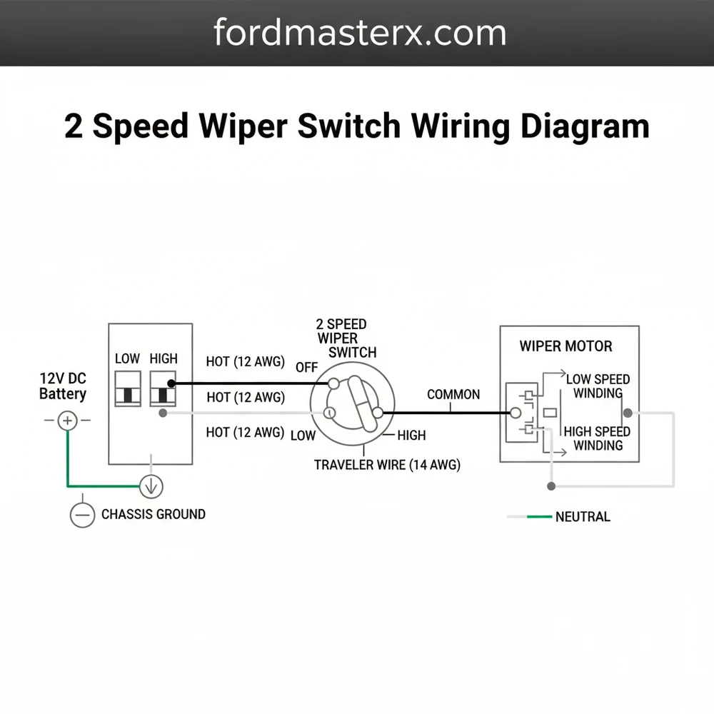
A 2 speed wiper switch wiring diagram illustrates the connection between the power source, switch, and motor. Typically, a hot wire feeds the common terminal, while separate outputs connect to the low and high-speed windings. A ground wire ensures the circuit completes, allowing the traveler wire to toggle between the two speed settings effectively.
📌 Key Takeaways
- Visualizes the electrical path for controlling dual-speed motor windings
- The common terminal is the critical entry point for battery power
- Always disconnect the battery to prevent shorts during installation
- Useful for automotive restorations, marine setups, and heavy machinery
- Helps diagnose whether a failure is in the switch or the motor itself
Understanding the intricacies of a 2 speed wiper switch wiring diagram is essential for any automotive restoration or repair project involving a vehicle’s visibility system. When the rain begins to fall, the reliability of your wipers depends entirely on the integrity of the electrical connections between the battery, the switch, and the wiper motor. A proper diagram serves as a roadmap, guiding you through the complex path of current as it moves from a simple power source to a mechanical movement. This article provides a comprehensive breakdown of terminal identification, wire color-coding, and the sequential steps required to wire a 2-speed system successfully. By the end of this guide, you will be equipped to handle installation and troubleshooting with the confidence of a professional technician.
Understanding the 2 Speed Wiper Switch Wiring Diagram Components
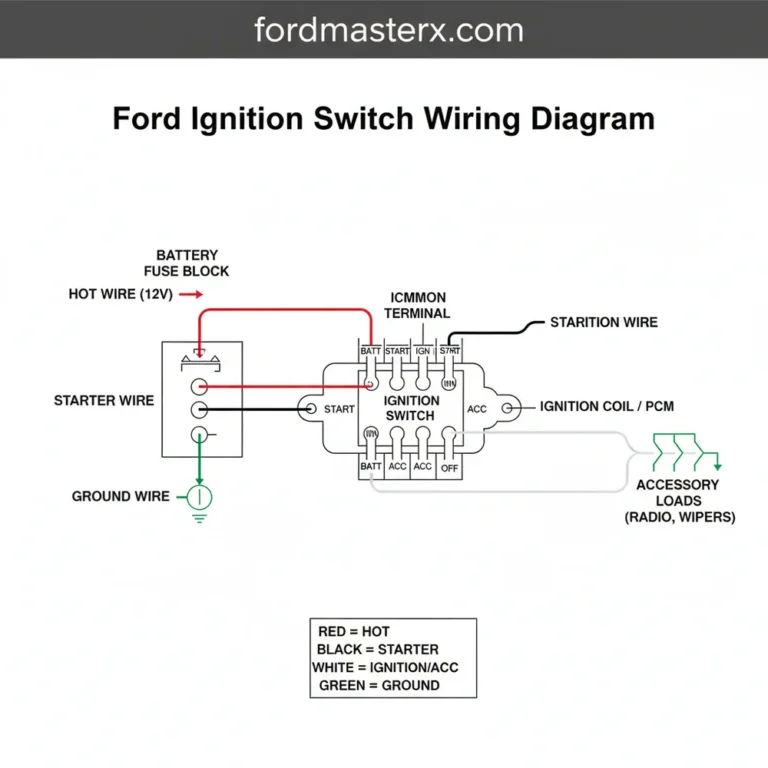
A 2 speed wiper switch wiring diagram is more than just a collection of lines and symbols; it is a functional representation of how electrical energy is converted into mechanical motion. Most standard 2-speed systems utilize a rotary or toggle switch that manages four or five distinct connections. The core of this system is the common terminal, which serves as the primary entry point for electricity. Depending on the manufacturer, this terminal may be labeled as “B” for Battery or “L” for Line.
In a typical diagram, you will observe the hot wire connecting the fuse block to the switch. This wire is responsible for carrying 12-volt voltage to the switch housing. Inside the switch, the internal contacts bridge this power to either the “Low” or “High” speed outputs. These outputs are connected to the motor via a traveler wire, which carries the specific signal required to activate different sets of brushes within the wiper motor. The “Low” speed circuit typically passes through a resistor or a specific winding, while the “High” speed circuit allows for maximum current flow to the motor.
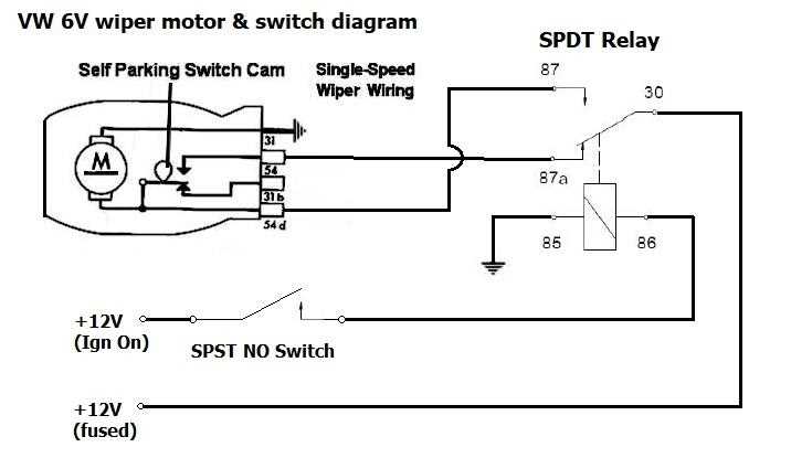
Another vital element in the diagram is the “Park” circuit. This is often the most misunderstood part of the 2 speed wiper switch wiring diagram. The park feature requires a constant hot wire connection that remains active even when the switch is in the “Off” position. This allows the motor to continue rotating until the wipers reach their designated resting point at the bottom of the windshield. A brass screw on the back of many aftermarket switches often serves as the mounting point for this constant power or, in some cases, the dedicated ground wire connection.
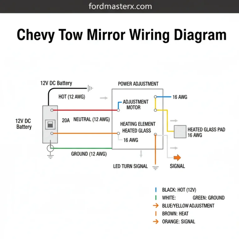
While most DC automotive systems use a ground-return through the chassis, some specialized or marine systems may refer to a neutral wire or a dedicated return path. Always confirm if your motor is “case-grounded” or if it requires a separate wire back to the battery negative.
The visual layout of the diagram will also specify the wire gauge required for the job. Because wiper motors draw significant amperage—especially when pushing heavy snow or clearing thick mud—the wiring must be thick enough to prevent overheating. Most diagrams will recommend a 14-gauge or 16-gauge wire to maintain consistent performance and safety.
Step-by-Step Guide to Using a 2 Speed Wiper Switch Wiring Diagram
Executing an installation based on a 2 speed wiper switch wiring diagram requires a methodical approach. Skipping a single connection can lead to a system that either won’t turn off, won’t park, or blows fuses instantly. Before you begin, gather the necessary tools: a high-quality crimping tool, a multimeter for testing voltage, and heat-shrink tubing to protect your connections from moisture.
- ✓ 14 or 16 gauge primary wire
- ✓ Insulated female spade connectors
- ✓ 10A or 15A inline fuse and holder
- ✓ Wire stripping tool
- ✓ Dielectric grease
1. Isolate the Power Supply
Safety is paramount. Begin by disconnecting the negative terminal of the vehicle battery. This prevents any accidental short circuits while you are working behind the dashboard. Locate a 12V ignition-switched power source on your fuse panel so the wipers only operate when the key is in the “On” or “Acc” position.
2. Mount the Switch and Motor
Ensure the switch is securely mounted in the dash. If your switch uses a brass screw for the housing ground, ensure it makes contact with a clean metal surface. Similarly, ensure the wiper motor is mounted firmly to the firewall, as vibration can lead to terminal fatigue over time.
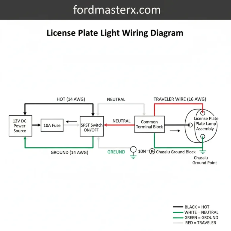
3. Connect the Ground Wire
Refer to your 2 speed wiper switch wiring diagram to determine the grounding method. If the motor is not self-grounding through the mounting bolts, run a dedicated ground wire from the motor’s ground terminal to a common grounding point on the chassis. Use a star washer to ensure the connection bites through any paint or rust.
4. Route the Primary Hot Wire
Run a hot wire from your fused power source to the common terminal on the switch. This provides the “juice” that the switch will distribute to the various speeds. If you are using a marine-style switch, this terminal is frequently marked with a “+” or “Line” symbol.
5. Install the Traveler Wires for Low and High Speeds
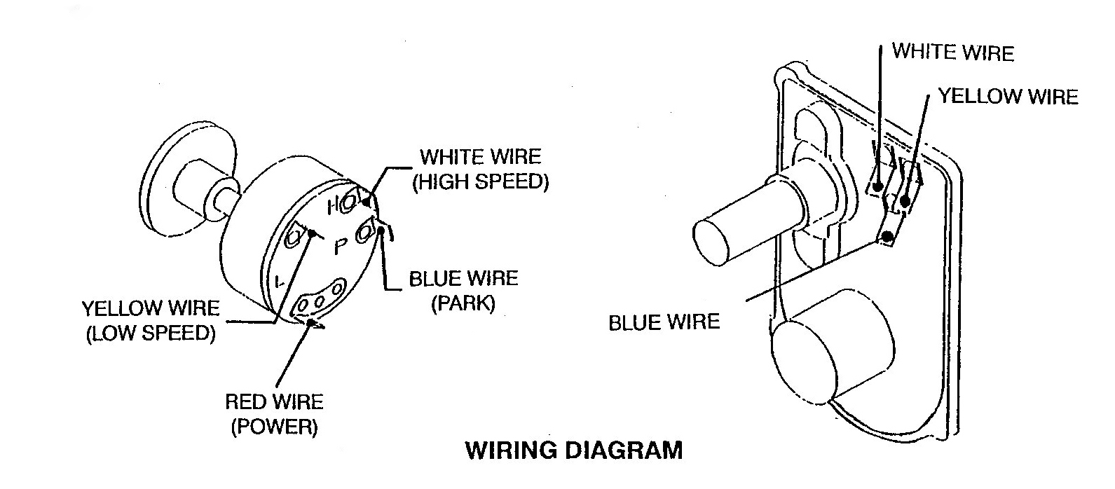
Identify the “Low” and “High” terminals on the motor and the switch. Connect them using two separate traveler wire runs. It is helpful to use different colors—such as blue for low and red for high—to avoid confusion. Strip about 1/4 inch of insulation, crimp the spade connector firmly, and slide it onto the corresponding terminal.
6. Configure the Park Circuit
This is where many DIYers struggle. The “Park” terminal on the motor must receive constant power through the switch when the wipers are in motion and a specific connection when the switch is turned off. Follow your diagram closely; usually, this involves a wire that bridges the motor’s park cam to the “Off” position on the switch.
7. Verification and Testing
Before tidying up the wires, reconnect the battery. Use a multimeter to verify that you have 12V voltage at the switch. Turn the switch to “Low” and ensure the blades move at a steady pace. Switch to “High” to verify increased speed. Finally, turn the switch to “Off” while the blades are in the middle of the glass; they should automatically return to the bottom position.
Never attempt to test the wiper motor without the arms attached or with the arms dry on a dirty windshield. The friction can cause a massive current spike that might blow the fuse or damage the internal park switch contacts.
Common Issues and Troubleshooting with a 2 Speed Wiper Switch Wiring Diagram
Even with a perfect 2 speed wiper switch wiring diagram, problems can arise due to aging components or poor connections. One of the most common complaints is a wiper motor that works but fails to “park” when turned off. This usually indicates that the constant hot wire going to the park terminal has a break in it, or the internal copper contact inside the motor is dirty or worn. Using the diagram, you can use a test light to see if power is reaching the park terminal even when the switch is off.
If the wipers operate very slowly, it is often a sign of a high-resistance ground or an insufficient wire gauge. Over time, the ground wire can corrode where it meets the chassis, leading to a drop in effective voltage. Another frequent issue is the “Low” speed failing while “High” speed continues to work. This points toward a failure in the specific traveler wire for the low-speed circuit or a burnt-out resistor in the switch itself.
In some cases, you might notice the switch getting hot to the touch. This is a red flag indicating that the motor is drawing too much current, possibly due to binding in the wiper linkage or a motor that is nearing the end of its life. Referencing your 2 speed wiper switch wiring diagram will help you isolate whether the fault lies in the wiring harness or the mechanical components of the system.
Tips and Best Practices for Long-Term Reliability
To ensure your wiper system remains reliable for years to come, there are several best practices you should follow during the installation of your 2 speed wiper switch wiring diagram. First, always use heat-shrink connectors rather than standard plastic ones. Heat-shrink provides a moisture-proof seal that prevents the green crust of corrosion from forming inside the wire crimp, which is the leading cause of electrical failure in older vehicles.
Label both ends of your wires with a small piece of masking tape or a wire marker. If you ever need to pull the dash apart in the future, you won’t have to guess which traveler wire is for High vs. Low speed.
Maintenance is also key. Every few years, check the brass screw and other terminals for tightness. The vibrations of the road can loosen these connections over time. Additionally, applying a small amount of dielectric grease to the terminals before sliding the connectors on will provide an extra layer of protection against oxidation.
When selecting components, avoid the cheapest “universal” switches unless they specifically match the amperage rating of your motor. High-quality switches are designed to handle the inductive kickback that occurs when a motor is switched off. If you are building a custom wiring harness, try to keep the runs as short as possible to minimize voltage drop, ensuring your motor always has the power it needs to clear the heaviest downpours. By strictly adhering to your 2 speed wiper switch wiring diagram and these best practices, you create a system that is as durable as it is functional.
Frequently Asked Questions
Where is the 2 speed wiper switch located?
The wiper switch is typically located on the vehicle’s dashboard or integrated into the steering column multifunction lever. In marine or industrial applications, it is often found on the main control panel. Identifying its location is the first step toward troubleshooting electrical issues or replacing the component entirely.
What does this wiring diagram show?
This wiring diagram illustrates the electrical path from the battery to the wiper motor. It shows how the switch selects between low and high-speed circuits. By following the diagram, you can identify which pins control specific speeds and ensure the park function returns the blades to the bottom.
How many connections does the wiper switch have?
A standard two-speed wiper switch usually features four to five connections. These include a main power input, a low-speed output, a high-speed output, and a terminal for the park circuit. Some systems also require a dedicated ground wire connection directly on the switch housing to complete the circuit.
What are the symptoms of a bad wiper switch?
Common symptoms include wipers that only work on one speed, blades that fail to return to the park position, or complete motor failure. If the motor hums but doesn’t move, the switch or its internal contacts may be corroded, preventing sufficient current from reaching the motor windings.
Can I replace the wiper switch myself?
Replacing a wiper switch is a manageable DIY task for most vehicle owners. With a basic understanding of electrical circuits and a few hand tools, you can swap the component in under an hour. Always remember to disconnect the battery before starting to prevent accidental shorts or blown fuses.
What tools do I need for wiper switch wiring?
To complete this task, you will need a set of screwdrivers to access the dash or column. A multimeter or test light is essential for verifying power at the terminals. Additionally, wire strippers and crimping tools are useful if you need to repair damaged connectors or wires.