1999 Ford F350 Fuse Box Diagram: Quick Identification Guide
The 1999 Ford F350 fuse box diagram identifies the interior panel under the steering column and the engine bay power distribution box. These charts help locate circuits for the ECU and OBD-II port, which are essential for troubleshooting power loss or reading a diagnostic code when the truck fails to start.
📌 Key Takeaways
- Identifies both interior and engine bay fuse locations
- Crucial for locating the fuse for the OBD-II diagnostic port
- Always disconnect the battery before replacing high-amp relays
- Fuses are color-coded based on their amperage rating
- Essential for clearing a check engine light caused by blown circuits
Finding yourself stranded with a non-responsive engine or a flickering dashboard in a heavy-duty truck can be an intimidating experience. For owners of the legendary Super Duty series, the 1999 Ford F350 fuse box diagram is the most essential document you can have in your glove box or saved on your phone. This diagram serves as the master key to your vehicle’s complex electrical grid, allowing you to pinpoint exactly which circuit has failed without having to test every single wire. By understanding the layout of these fuses and relays, you gain the ability to troubleshoot everything from a stubborn check engine light to a total loss of power to the ECU. This article provides a deep dive into the 1999 Ford F350 fuse box diagram, ensuring you have the knowledge to interpret these electrical maps, locate the necessary components, and perform safe, effective repairs on your own.
The 1999 Ford F350 utilizes two distinct fuse panels: the Passenger Compartment Fuse Panel, located inside the cabin, and the Power Distribution Box, located under the hood. Most diagnostic issues involving the OBD-II port are tied to the interior panel, while major engine components like the fuel pump and ECU are managed by the under-hood box.
Decoding the 1999 Ford F350 Fuse Box Diagram
The electrical architecture of the 1999 Ford F350 is divided into two primary hubs. The first is the Passenger Compartment Fuse Panel. This is located to the left of the steering column, tucked behind a removable plastic cover near your knees. This panel primarily handles “low-load” electronics. These include your instrument cluster, radio, interior lighting, and the power supply for the OBD-II diagnostic port. It is a common quirk in this model year that the fuse for the cigarette lighter also powers the OBD-II port; if you cannot pull a diagnostic code because your scanner won’t turn on, this interior panel is the first place you should look.
The second hub is the Power Distribution Box, located in the engine compartment on the driver’s side fender well. This box is designed for “high-load” circuits. It contains larger “Maxi” fuses and several high-voltage relays. Here, you will find the protection for the ECU (Engine Control Unit), the starter solenoid, the ABS pump, and the trailer tow relays. The diagram for this box is often printed on the underside of the plastic cover, but over time, heat and engine grime can make these markings illegible.
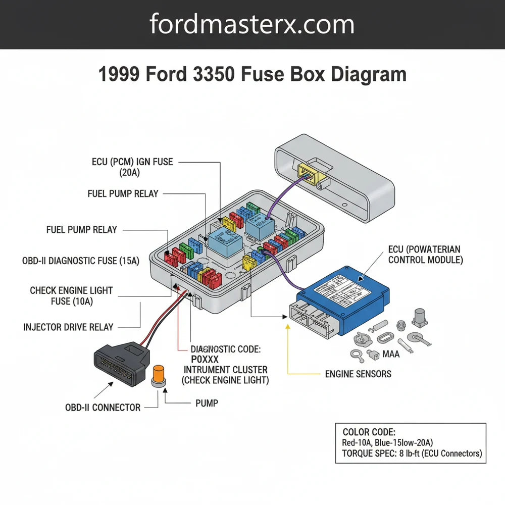
Visualizing the diagram requires understanding the grid system. Fuses are typically numbered from top-to-bottom or left-to-right. In the engine bay box, relays are larger square blocks, while fuses are smaller rectangular tabs. The interior panel uses mostly “Mini” fuses, which are color-coded by amperage: 10A is red, 15A is blue, 20A is yellow, and 30A is green. Knowing these color standards helps you quickly identify if someone has previously installed the wrong fuse in a slot, which can lead to electrical fires or component damage.
[DIAGRAM_PLACEHOLDER – 1999 FORD F350 FUSE BOX LAYOUT: INTERIOR PANEL (Fuses 1-31) and ENGINE PANEL (Fuses 1-30 + Relays)]
Never replace a blown fuse with one of a higher amperage. If a 10A fuse blows, replacing it with a 20A fuse allows twice as much current to flow through wires not designed for it, which can melt the harness or cause a fire.
Step-By-Step Guide to Using the Diagram and Replacing Fuses

Navigating the 1999 Ford F350 fuse box diagram and performing a replacement is a straightforward process if you follow a logical sequence. Whether you are addressing a check engine light or a dead accessory, follow these steps to ensure a safe repair.
- ✓ Step 1: Preparation and Safety. Ensure the ignition is completely off and the keys are removed. If you are working on high-amperage fuses in the engine bay, it is a best practice to disconnect the negative battery terminal. This prevents accidental shorts while you are probing the box with tools.
- ✓ Step 2: Locate the Correct Panel. Determine if the failed component is an interior accessory or an engine-critical part. For example, if the coolant flow sensor is malfunctioning, start with the engine bay box. If the dashboard lights are out, go to the interior panel.
- ✓ Step 3: Consult the Diagram. Match the fuse number from the diagram to the physical location in the box. For instance, in the interior panel, Fuse #3 (20A) is responsible for the Cigar Lighter and Data Link Connector (OBD-II). If your scanner cannot read a diagnostic code, this is your target.
- ✓ Step 4: Inspect the Fuse. Use a plastic fuse puller (usually found inside the fuse box cover) to remove the fuse. Hold it up to a light source. If the metal bridge inside the plastic is broken or there is a dark scorch mark, the fuse is blown.
- ✓ Step 5: Test the Circuit. Using a multimeter set to the continuity or DC voltage setting, check the “legs” of the fuse socket. With the fuse removed and the ignition on, one side of the socket should show 12 volts. If there is no power to the socket, the issue may be further up the line toward the battery or a primary relay.
- ✓ Step 6: Replace and Verify. Insert a new fuse of the exact same amperage rating. Reconnect the battery if it was disconnected. Note that for battery terminals, you should follow the proper torque spec (usually around 10-13 lb-ft) to ensure a solid connection that won’t vibrate loose.
- ✓ Step 7: Clear Codes. If the blown fuse caused a check engine light, use an OBD-II scanner to clear the diagnostic code. Start the engine and verify that the component is functioning and that no new lights appear on the dash.
Common Troubleshooting and Electrical Issues

The 1999 Ford F350 is a workhorse, but its age means electrical gremlins are common. One of the most frequent issues is a “crank but no start” condition. While you might immediately worry about a timing chain failure or a broken accessory belt, you should first check the Power Distribution Box. Fuse #24 (30A) provides power to the PCM (Power Control Module/ECU). If this fuse is blown, the engine will spin but will never fire because the computer isn’t sending signals to the injectors.
Another common symptom is the “ghost” check engine light. Sometimes a sensor fuse, such as those related to the HEGO (Heated Exhaust Gas Oxygen) sensors, will blow. This triggers a specific diagnostic code that might lead you to replace an expensive sensor, when in reality, a $0.50 fuse was the culprit. Additionally, if you experience issues with cooling, check the relays for the electric fans (if equipped) or the sensors monitoring coolant flow. A faulty relay is often the cause of overheating in stationary traffic, rather than a mechanical pump failure.
If you find that a specific fuse (like the one for the trailer tow lights) blows repeatedly, check the wiring harness near the rear bumper. Frayed wires there often short out against the frame, causing the fuse to trip as a safety measure. The diagram helps you isolate which circuit to trace.
Maintenance Tips and Best Practices
To keep your F350’s electrical system in peak condition, regular inspection of the fuse boxes is highly recommended. Over time, the engine bay box can accumulate moisture or corrosion, especially in salt-belt states. Using a small amount of dielectric grease on the legs of the fuses can prevent oxidation and ensure a consistent connection.
When performing maintenance, always check your accessory belt. A worn belt can cause the alternator to undercharge the battery, leading to low-voltage conditions that can prematurely wear out relays or cause the ECU to behave erratically. While the 1999 F350 engines (specifically the 7.3L Diesel and the V10) are famously durable, they rely heavily on steady voltage.
If you are upgrading your truck with aftermarket lighting or winches, avoid tapping into existing circuits found on the 1999 Ford F350 fuse box diagram. Instead, run a dedicated wire from the battery with its own inline fuse. This protects the factory wiring harness from being overloaded. High-quality components are also vital; avoid “unbranded” fuses from bargain bins, as they often fail to trip at the rated amperage, which defeats their entire purpose.
Finally, keep a printed copy of the 1999 Ford F350 fuse box diagram in your vehicle. In a breakdown scenario where your phone battery might be low or you lack cellular service, having a physical copy of the diagram can be the difference between getting back on the road and calling a tow truck. By mastering this diagram, you ensure your Super Duty remains the reliable tool it was built to be.
Step-by-Step Guide to Understanding the 1999 Ford F350 Fuse Box Diagram: Quick Identification Guide
Identify the electrical issue – Determine which component is failing to narrow down the specific fuse circuit.
Locate the fuse panel – Open the interior cover under the steering wheel or the engine bay distribution box.
Understand how the diagram works – Match the numbered slot on the physical panel to the diagram’s circuit description.
Apply the fuse puller – Carefully remove the suspected fuse to inspect the internal metal filament for breaks.
Verify that the amperage matches – Ensure the replacement fuse has the same color and numerical rating as the original.
Complete the repair – Reinstall the panel cover and start the vehicle to check if the circuit is restored.
Frequently Asked Questions
Where is the 1999 Ford F350 fuse box located?
The primary fuse box is located under the dashboard to the left of the steering column. A secondary high-power distribution box is located in the engine compartment on the driver’s side wheel well. Both contain essential fuses for the ECU and various cabin electronics.
What does the 1999 Ford F350 fuse box diagram show?
The diagram illustrates the layout, numbering, and amperage of every fuse and relay. It specifically identifies which circuit controls components like the fuel pump, headlights, and the OBD-II system, allowing for targeted troubleshooting when electrical systems fail or a diagnostic code is triggered.
How many pins does the OBD-II diagnostic port have?
The OBD-II port, powered through the fuse box, has 16 pins. If the port lacks power, it is often due to a blown cigar lighter fuse (Fuse 3 in the interior panel), which prevents scan tools from communicating with the ECU to read engine data.
What are the symptoms of a bad ECU fuse?
A blown ECU fuse will typically cause the engine to crank but not start, or result in an immediate engine stall. You may also see a check engine light or find that your scan tool cannot establish a connection with the vehicle’s computer system.
Can I replace Ford F350 fuses myself?
Yes, replacing a fuse is a simple DIY task. After identifying the correct fuse using the 1999 Ford F350 fuse box diagram, simply pull the old fuse out and insert a new one of the same amperage. Always ensure the ignition is turned off first.
What tools do I need for fuse box maintenance?
You need a plastic fuse puller tool and a digital multimeter for testing continuity. If you are replacing the entire fuse block or tightening battery terminals, ensure you follow the manufacturer’s torque spec (usually 5-10 lb-ft for small electrical fasteners) to prevent stripping the threads.


