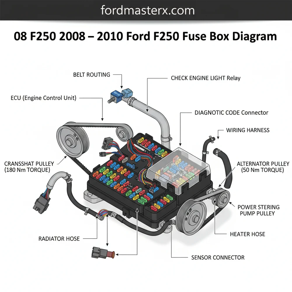
08 F250 2008 -2010 Ford F250 Fuse Box Diagram Guide
The 2008-2010 Ford F250 features two main fuse panels: the passenger compartment fuse box located behind the kick panel and the power distribution box under the hood. This diagram identifies specific fuses for the ECU, OBD-II port, and lighting systems, allowing for rapid electrical troubleshooting and repair.
📌 Key Takeaways
- Identifying circuit protection for vehicle electronics and power distribution.
- The ECU and OBD-II port fuses are the most critical components for engine operation.
- Always use the correct amperage rating to avoid electrical fires or circuit damage.
- Carry a spare fuse kit and a basic puller tool for emergency roadside repairs.
- Use this diagram when facing a check engine light or unresponsive electrical components.
The 2008 to 2010 Ford F-250 Super Duty represents a significant era for Ford trucks, featuring the introduction of the 6.4L Power Stroke diesel engine and a modernized interior. For DIY enthusiasts, maintaining the electrical system of these heavy-duty machines is a critical skill. Whether you are dealing with a non-responsive radio, a dead trailer plug, or a mysterious starting issue, your first line of defense is the fuse box. Understanding the 2008-2010 Ford F-250 fuse box diagram is more than just finding a blown wire; it is about navigating the complex nervous system of a vehicle designed for high-stress work and towing. These trucks utilize a dual-box system: the Passenger Compartment Fuse Panel (often called the Smart Junction Box) and the Power Distribution Box located under the hood.
Main Locations and Features
In the 2008, 2009, and 2010 F-250 models, Ford centralized the electrical protection into two primary locations. Knowing exactly where these are and how they are constructed will save you significant time during a roadside repair.
1. The Passenger Compartment Fuse Panel (Interior): This box is located behind the kick panel on the passenger side of the truck. To access it, you must remove the trim panel by pulling it toward the rear of the vehicle and then removing the fuse box cover. This box houses “Mini” fuses and “Low-profile mini” fuses, which typically range from 2A to 30A. It controls interior functions like the instrument cluster, interior lighting, power windows, and the OBD-II diagnostic port.
2. The Power Distribution Box (Engine Bay): Located under the hood on the driver’s side, tucked near the firewall and the brake fluid reservoir, this box handles high-current circuits. It contains larger “J-Case” cartridge fuses and “Full-ISO” relays. This box is responsible for the heavy hitters: the fuel pump, the PCM (Powertrain Control Module), trailer tow relays, and the cooling fans. The cover is secured by plastic tabs that require a firm squeeze to release.
Specific Measurements and Components:
The fuses themselves follow standard industry sizing. A standard mini fuse used in the interior panel measures approximately 10.9mm in width. The J-case fuses in the engine bay are much larger (approx. 14.1mm wide) and are designed to handle currents up to 60A or 80A. The wiring harnesses feeding into these boxes often use high-gauge copper wire, with colors like Red/White for constant power and Black/Green for specific ground circuits depending on the trim level.
How to Use and Read the Fuse Box Diagram

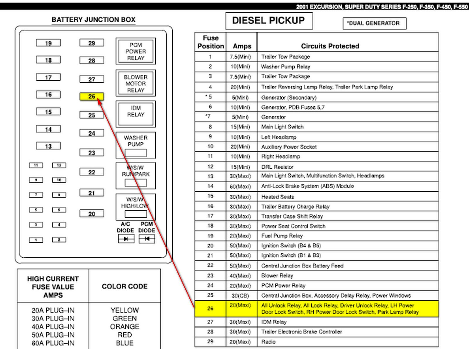
Reading the 2008-2010 F-250 fuse box diagram requires matching the numerical layout on the plastic cover (or in your owner’s manual) with the physical orientation of the box. Ford uses a grid system, but the numbers are not always perfectly sequential from left to right.
Common Interior Fuse Mappings (Passenger Side):
- Fuse 1 (30A): Moonroof / Power Windows.
- Fuse 2 (20A): Power Seats.
- Fuse 14 (10A): Interior Lighting and Glove Box.
- Fuse 20 (15A): Diagnostic Connector (OBD-II). (If your code reader won’t power up, check this fuse!)
- Fuse 41 (15A): Radio/CD Player and Mirror logic.
Common Engine Bay Fuse Mappings (Under Hood):
- Fuse 4 (20A): Fuel Pump Relay.
- Fuse 7 (30A): Starter Solenoid.
- Fuse 13 (30A): Trailer Tow Electric Brake.
- Fuse 26 (10A): PCM (Powertrain Control Module) Keep Alive Power.
- Fuse 76 (20A): Auxiliary Power Point (Cigarette Lighter).
When reading the diagram, look for the “Ampere Rating” (A) printed on top of the fuse. Ford uses a color-coding system that is universal: Red is 10A, Blue is 15A, Yellow is 20A, and Green is 30A. Never replace a fuse with one of a higher amperage; doing so can lead to melted wires or even an electrical fire in your 6.4L or 5.4L engine harness.
Practical Tips for DIY Maintenance
Maintaining the electrical health of a decade-old Super Duty requires a few specialized tools and habits. Because these trucks are often used for towing, the fuse boxes are subject to vibration and moisture, which can lead to loose connections or corrosion.
- Use the Right Puller: The interior fuse box is cramped. Use the white plastic fuse puller tool usually stored on the inside of the fuse box cover. If it’s missing, a pair of needle-nose pliers with insulated handles is essential.
- Apply Dielectric Grease: If you live in a “salt belt” state or use your F-250 for boat launching, apply a small amount of dielectric grease to the terminals of the under-hood fuses. This prevents oxidation and ensures a solid connection in the Power Distribution Box.
- Carry Spares: The 2008-2010 models use three different types of fuses (Mini, J-Case, and Relays). Keep a small assortment kit in your center console, specifically focusing on 10A, 15A, and 20A mini fuses, as these are the most likely to blow during accessory installation or trailer mishaps.
- Check Trailer Wiring First: If you keep blowing the “Trailer Tow” fuses in the engine bay, the problem is likely a short in the 7-way plug at the bumper, not the truck’s internal wiring. Inspect the back of the plug for green crusty corrosion.
Troubleshooting Common Electrical Issues
When a circuit fails in your F-250, follow this logical progression to diagnose the issue using the fuse box diagram as your map.
1. Visual Inspection: Pull the suspected fuse and look at the metal bridge inside the plastic. If the bridge is broken or the plastic is charred/cloudy, the fuse is blown. However, fuses can sometimes look “good” but still be hairline-fractured.
2. The Multimeter Test: This is the most reliable DIY method. Set your multimeter to “Continuity” or “Ohms.” Touch the probes to the two small metal test points on the top of the fuse while it is still plugged in. If the meter beeps, the fuse is good. If there is no beep, the circuit is open (blown).
3. Relays vs. Fuses: If the fuse is intact but the component (like the AC compressor or the starter) still won’t work, the relay might be the culprit. A quick DIY trick is to find another relay in the box with the same part number—such as the horn relay—and swap them. If the component starts working, you know you need a new relay. In the 2008-2010 F-250, many of these are the “Half-ISO” small black cubes.
4. Parasitic Draw: If your truck batteries are dead every morning, you may have a parasitic draw. Use the fuse box diagram to pull fuses one by one while monitoring an ammeter connected to the battery. When the amperage drop occurs, you have identified the specific circuit that is “leaking” power while the truck is off.
Conclusion:
The 2008-2010 Ford F-250 fuse box system is robust, but it requires respect and understanding. By keeping a copy of the diagram handy and knowing the locations of the Passenger Compartment and Power Distribution boxes, you can tackle almost any electrical gremlin that comes your way. Whether you are a weekend warrior or a professional contractor, mastering your fuse box is the key to keeping your Super Duty on the road and out of the expensive repair shop.
Step-by-Step Guide to Understanding the 08 F250 2008 -2010 Ford F250 Fuse Box Diagram Guide
Identify the electrical issue, such as a dead radio, non-functional lights, or a check engine light.
Locate the passenger-side kick panel or the engine bay power distribution box cover to access the fuses.
Understand how the diagram numbering corresponds to the physical slots in the fuse box layout.
Apply the fuse puller to remove the suspected fuse and check for a broken or burnt metal filament.
Verify that the replacement fuse matches the correct amperage rating listed in the manufacturer’s diagram.
Complete the repair by retesting the component and clearing any remaining diagnostic codes via the OBD-II port.
Frequently Asked Questions
Where is the fuse box located on a 2008-2010 F250?
The 2008-2010 Ford F250 has two primary locations. The interior fuse panel is behind the passenger-side kick panel, while the high-power distribution box is under the hood on the driver’s side near the firewall. Both contain essential fuses for everything from the ECU to the radio.
What does the fuse box diagram show?
This diagram provides a detailed map of the fuse and relay layout. It identifies the amperage rating and specific function for every circuit, such as the OBD-II diagnostic port, headlamps, and powertrain control module, helping you quickly isolate electrical failures without the need for professional equipment.
How many fuses and relays does the F250 have?
The exact number varies by trim and engine, but the interior panel typically houses around 48 fuses, while the engine bay power distribution box contains roughly 60 fuses and several large relays. These manage high-draw components like the fuel pump, trailer tow lights, and the cooling fans.
What are the symptoms of a blown ECU or OBD-II fuse?
If the ECU fuse blows, the engine will crank but not start, or stall unexpectedly. A blown OBD-II fuse prevents scanners from communicating with the vehicle, often triggering a check engine light that cannot be cleared until the fuse is replaced and the diagnostic code is pulled and addressed.
Can I replace these fuses myself?
Yes, replacing fuses is a basic DIY task. Most F250 owners can swap fuses in minutes using the plastic puller tool located inside the fuse box cover. However, if a fuse blows repeatedly, you likely have a short circuit that requires more advanced electrical diagnosis to fix properly.
What tools do I need for fuse box maintenance?
You will need a fuse puller tool or needle-nose pliers, a multimeter for testing continuity, and a diagnostic scanner to check for a diagnostic code. If working on the battery terminals or mounting brackets, ensure you follow the specific torque spec for your hardware to maintain secure connections.


