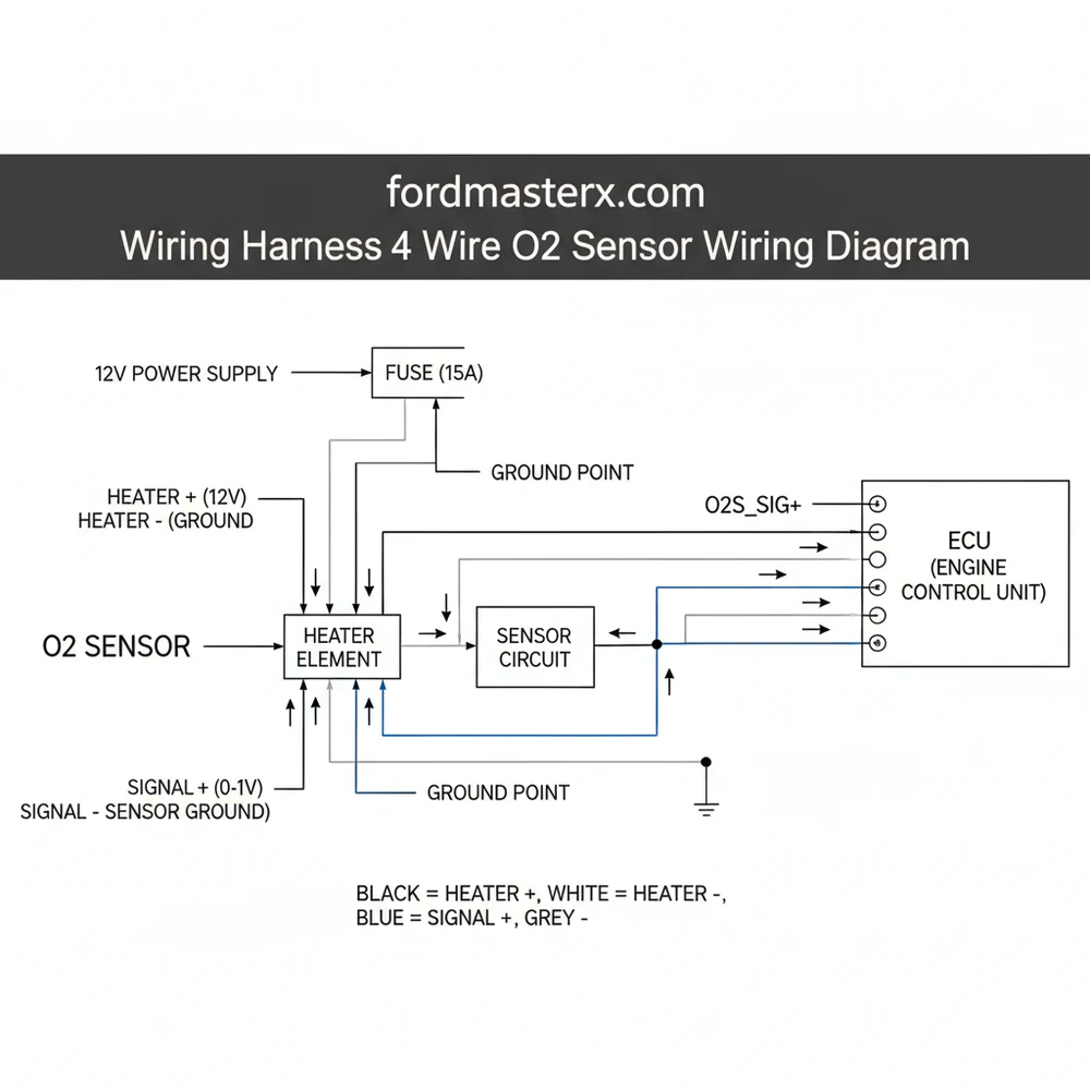
Wiring Harness 4 Wire O2 Sensor Wiring Diagram Guide
This wiring harness 4 wire o2 sensor wiring diagram consists of two heater wires and two signal wires. The heater circuit uses a hot wire for power and a ground wire, while the signal circuit acts as a traveler wire sending voltage data to the ECU’s common terminal to regulate the air-fuel mixture.
📌 Key Takeaways
- Identify the two heater wires which are usually the same color
- Distinguish between the signal high and the signal low wires
- Ensure the ground wire has a clean, rust-free connection point
- Check for 12V on the heater circuit when the ignition is on
- Use this diagram when diagnosing P0135 or P0141 oxygen sensor codes
Finding an accurate wiring harness 4 wire o2 sensor wiring diagram is the first step toward resolving engine performance issues, clearing stubborn check engine lights, and improving fuel efficiency. When your vehicle’s Engine Control Unit (ECU) cannot communicate effectively with the oxygen sensor, the entire combustion process suffers. This diagram serves as a technical map, showing you exactly where each wire leads and what role it plays in the closed-loop feedback system. By understanding the specific layout of your harness, you can perform repairs or installations with confidence, ensuring that your vehicle meets emissions standards while maintaining peak horsepower. In this guide, you will learn how to identify wire functions, interpret color codes, and execute a flawless installation.
Decoding the Wiring Harness 4 Wire O2 Sensor Wiring Diagram
The primary purpose of a wiring harness 4 wire o2 sensor wiring diagram is to distinguish between the two distinct circuits within a single sensor housing: the heater circuit and the signal circuit. Unlike older single-wire sensors that relied on the exhaust pipe for grounding, the 4-wire variant provides its own dedicated grounds, which leads to much higher accuracy. The diagram typically breaks down the four wires into specific functional pairs.
Two of the wires are dedicated to the internal heating element. This heater is essential because an oxygen sensor must reach approximately 600 degrees Fahrenheit before it can produce a reliable voltage signal. In most diagrams, the heater wires are non-polarized, meaning they can often be swapped with one another without damaging the system, provided they remain within the heater circuit loop. These wires are essentially the “hot wire” and “neutral wire” of the sensor’s internal oven.
The remaining two wires are the signal wire and the sensor ground wire. The signal wire is the “traveler wire” of the data world, carrying a low-voltage electrical charge (usually between 0.1V and 0.9V) back to the ECU. The sensor ground ensures that the delicate signal is not distorted by electrical noise from the engine block. While residential electrical systems might use a brass screw to secure a common terminal ground, automotive sensors use a dedicated pin within the harness connector to maintain a clean reference point.
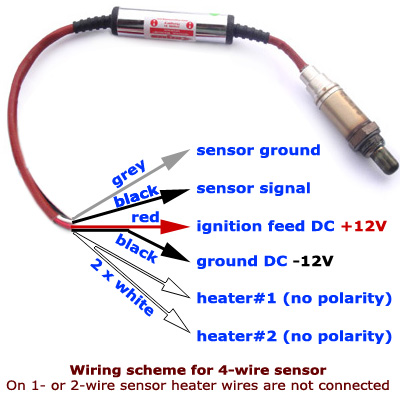
Most universal 4-wire oxygen sensors follow a standard color convention, but OEM (Original Equipment Manufacturer) harnesses may vary. Always verify if your wires are Bosch-style (two whites, one black, one grey) or Denso-style (two blacks, one blue, one white) before cutting or splicing.
[DIAGRAM_PLACEHOLDER: A detailed illustration showing a 4-wire O2 sensor connector. Labels point to Pin 1 (Heater +), Pin 2 (Heater -), Pin 3 (Signal Ground), and Pin 4 (Signal Output). Color coding shows two white wires for the heater, one grey wire for ground, and one black wire for the signal.]
Step-by-Step Installation Using the Wiring Diagram
Successfully implementing the information from a wiring harness 4 wire o2 sensor wiring diagram requires a methodical approach. Follow these steps to ensure your sensor is wired correctly and functions within the proper voltage parameters.
- 1. Tool Preparation and Safety: Gather a high-quality digital multimeter, wire strippers, heat-shrink tubing, and a soldering iron. Ensure the vehicle is completely cool, as exhaust components reach extreme temperatures. Disconnect the negative battery terminal to prevent any accidental short circuits while you are working with the hot wire of the heater circuit.
- 2. Locate the Connector and Identify Wires: Unplug the old sensor from the main vehicle harness. Compare the colors of the wires on the vehicle side to those on the sensor side. Use your diagram to identify the common terminal for the ground and the power feed for the heater. If the colors do not match exactly, you must use a multimeter to find the two wires that show resistance (these are your heater wires).
- 3. Map the Heater Circuit: Identify the 12V supply wire from the ECU. This is the equivalent of a hot wire in a standard AC circuit. In a 4-wire O2 system, this wire provides the voltage necessary to warm the ceramic element. Connect this to one of the heater wires on your new sensor. Connect the second heater wire to the heater ground wire in the harness.
- 4. Establish the Signal and Ground Connections: Connect the signal wire (often the “traveler” that sends data) to the ECU input. Finally, connect the sensor ground wire. It is vital that this ground is secure; while you aren’t using a brass screw on a terminal block, the pin connection must be tight and free of corrosion to prevent “signal drift.”
- 5. Secure and Insulate: If you are using a universal sensor, use solder and heat-shrink tubing for every connection. Never use wire nuts or simple electrical tape, as the high-vibration environment of an engine will cause these to fail. Ensure the wire gauge is consistent with the original harness to prevent resistance changes.
- 6. Final Testing: Reconnect the battery and start the engine. Use your multimeter to back-probe the signal wire. You should see the voltage oscillating between 0.1V and 0.9V once the engine reaches operating temperature. This confirms the wiring harness 4 wire o2 sensor wiring diagram was followed correctly.
Never apply grease or cleaner directly to the sensor tip or the vent holes. Oxygen sensors “breathe” through the wiring harness itself in some designs; clogging these pathways with silicone or grease can lead to immediate sensor failure.
Troubleshooting Common Wiring Issues

Even with a perfect wiring harness 4 wire o2 sensor wiring diagram, problems can arise due to age, heat, or environmental factors. One of the most common issues is a “Heater Circuit Malfunction” (Diagnostic Trouble Codes P0135 or P0141). This usually indicates that the 12V hot wire feeding the heater has been compromised or the internal resistance of the heater element has gone out of spec.
Another frequent problem is signal interference. If the signal ground wire is damaged, the ECU may receive an erratic voltage reading, causing the engine to run too “rich” or too “lean.” You can use the diagram to trace the ground wire back to the chassis or the ECU’s common terminal. If you find high resistance (above 0.5 ohms) on the ground path, the sensor will not function accurately.
Watch for physical signs of damage, such as frayed insulation or melted wires near the exhaust manifold. If the wire gauge appears thinner than the original or if the insulation is brittle, the internal copper may be corroded. If troubleshooting with a multimeter and the wiring diagram does not reveal the source of the fault, the internal ceramic element of the sensor may be poisoned by oil or coolant, requiring a full replacement.
When testing, check the voltage at the harness plug rather than just the sensor. This helps determine if the fault lies in the sensor itself or the vehicle’s side of the wiring harness.
Best Practices for O2 Sensor Maintenance
Maintaining the integrity of your wiring harness 4 wire o2 sensor wiring diagram connections is essential for long-term vehicle health. One of the best practices is to use anti-seize lubricant on the threads of the sensor before installation. However, ensure that the lubricant does not touch the sensor snout, as this will contaminate the platinum electrodes.
When it comes to wire management, always route the harness away from direct contact with the exhaust pipe. Use high-temperature zip ties or OEM clips to secure the “traveler wire” and heater leads. This prevents the insulation from melting and creating a short circuit between the hot wire and the chassis ground.
- ✓ Use oxygen-sensor-safe RTV silicone if any sealing is required nearby.
- ✓ Ensure the wire gauge of any patch wires matches the factory specifications (usually 18 or 20 AWG).
- ✓ Regularly inspect the connector for “green crusties” (corrosion) which can increase resistance.
- ✓ Choose high-quality sensors from reputable brands like Bosch, Denso, or NGK/NTK to ensure the internal heater resistance matches your ECU’s expectations.
By strictly adhering to your wiring harness 4 wire o2 sensor wiring diagram and maintaining clean, secure connections at every terminal, you ensure that your vehicle’s fuel management system operates as the engineers intended. Whether you are replacing a faulty component or performing a custom engine swap, the key to success lies in the details of the wire colors and their corresponding pins. Proper wiring not only saves you money at the gas pump but also extends the life of your catalytic converter, making this a vital skill for any DIY mechanic or automotive enthusiast.
Frequently Asked Questions
Where is the 4 wire o2 sensor located?
The 4-wire O2 sensor is located in the exhaust system. Sensor 1 is found in the exhaust manifold before the catalytic converter, while Sensor 2 is located after the converter. They are threaded directly into the exhaust pipe to monitor oxygen levels in the gas stream.
What does a wiring harness 4 wire o2 sensor wiring diagram show?
The diagram illustrates the four specific electrical paths: the 12V heater power, the heater ground, the signal output to the ECU, and the sensor ground. It helps identify which pin on the connector corresponds to each function, preventing cross-wiring that could damage the vehicle’s computer.
How many connections does a 4 wire o2 sensor have?
A 4-wire O2 sensor has four distinct electrical connections. Two wires are dedicated to the internal heating element to help the sensor reach operating temperature quickly. The remaining two wires are the signal wire and the ground wire, which provide oxygen data to the engine control module.
What are the symptoms of a bad 4 wire o2 sensor?
Common symptoms include a lit check engine light, a significant drop in fuel efficiency, and a rough engine idle. You may also notice a ‘rotten egg’ smell from the exhaust or engine hesitations during acceleration, as the ECU cannot properly calculate the air-fuel ratio.
Can I replace a 4 wire o2 sensor wiring harness myself?
Yes, replacing the sensor or repairing the wiring harness is a manageable DIY task. It requires basic tools and the ability to follow a wiring diagram. However, ensure the vehicle is cool before touching the exhaust and use high-temp anti-seize on the sensor threads during installation.
What tools do I need for O2 sensor wiring?
You will need a dedicated O2 sensor socket (22mm or 7/8 inch), a ratchet, and a digital multimeter to test for continuity and voltage. If repairing the harness, you will also need wire strippers, heat-shrink tubing, and a crimping tool for secure, weather-resistant connections.