Vacuum Advance Holley Carb Vacuum Diagram: Easy Setup Guide
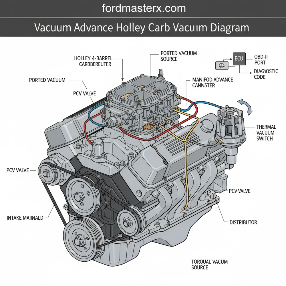
This diagram illustrates the connection between the distributor vacuum advance canister and the specific ports on a Holley carburetor. To set it up, connect the distributor line to the timed (ported) vacuum nipple, usually located on the side of the primary metering block, to ensure advance only occurs above idle.
📌 Key Takeaways
- Identifies the difference between ported and manifold vacuum sources
- The distributor vacuum canister is the primary component for ignition timing adjustment
- Incorrect routing can cause overheating or poor off-idle acceleration
- Use a vacuum gauge to confirm port behavior before final installation
- Consult this diagram when replacing a carburetor or tuning for fuel efficiency
Achieving the perfect engine tune-up often begins with understanding how your ignition system communicates with your fuel delivery system. For many classic car enthusiasts and DIY mechanics, finding a clear vacuum advance Holley carb vacuum diagram is the first step toward solving performance issues like hesitation, poor fuel economy, or overheating. This guide is designed to provide you with a comprehensive visual and technical breakdown of how to properly route your vacuum lines. By the end of this article, you will understand the critical differences between ported and manifold vacuum, how to identify specific ports on your Holley carburetor, and how to ensure your ignition timing is advancing exactly when it should for peak efficiency.
Understanding the Vacuum Advance Holley Carb Vacuum Diagram
When looking at a standard Holley carburetor—whether it is a 4150, 4160, or a modern Avenger series—the vacuum ports are strategically placed to provide different types of engine signals. A proper vacuum advance Holley carb vacuum diagram distinguishes between three primary sources of vacuum: Timed Spark (Ported), Full Manifold, and the PCV (Positive Crankcase Ventilation) port.
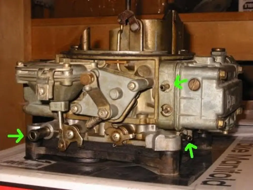
The Timed Spark port is typically located on the side of the primary metering block, often on the passenger side of the vehicle. This port is positioned just above the throttle plates. When the engine is at idle, the throttle plates block this port, meaning there is zero vacuum signal reaching the distributor. As you tip into the throttle, the plates move past the port, “turning on” the vacuum advance. Conversely, the Full Manifold vacuum port is located on the baseplate or the rear of the carburetor. This port provides a constant vacuum signal regardless of throttle position, which is often used for brake boosters or specific performance timing curves.
[DIAGRAM: HOLLEY VACUUM PORT IDENTIFICATION]
Top View and Side Profile of a Holley 4-Barrel Carburetor
- ● PORT A (Passenger Side): Timed Spark / Ported Vacuum (To Distributor Advance)
- ● PORT B (Baseplate Front): Full Manifold Vacuum (To Accessories or Tuning)
- ● PORT C (Baseplate Rear): Large 3/8″ Port (To PCV Valve)
- ● PORT D (Rear Small): Power Brake Booster / Vacuum Modulator
In modern applications where an ECU (Engine Control Unit) manages fuel, these mechanical ports might be capped off in favor of electronic sensors. However, for traditional setups, identifying these color-coded or labeled locations on the diagram is essential to prevent “pinging” or detonation under load.
Most street-driven Holley carburetors perform best when the distributor’s vacuum advance canister is connected to the “Timed Spark” port. This prevents too much timing at idle, which can cause the engine to run hot or stumble when coming to a stop.
Step-by-Step Installation and Calibration Guide
Connecting your vacuum advance using the diagram requires a methodical approach to ensure there are no leaks and that the signal is consistent. Before you begin, ensure the engine is cool to the touch and that the vehicle is in park with the emergency brake engaged.
- 1. Identify the Distributor Type: Locate the vacuum canister on your distributor. It is the metal “UFO-shaped” component with a single nipple. Ensure the internal diaphragm is holding vacuum by applying a handheld vacuum pump; the internal plate should move and hold steady.
- 2. Select the Correct Carburetor Port: Referencing your vacuum advance Holley carb vacuum diagram, locate the small port on the side of the primary metering block. This is almost always the Timed Spark port. If your carb has multiple small ports, the one higher up on the body is usually the ported source.
- 3. Measure and Cut Vacuum Line: Use high-quality rubber vacuum hose. Ensure the hose has enough slack to account for engine torque and vibration, but not so much that it interferes with the accessory belt or rests on hot exhaust manifolds.
- 4. Inspect Related Systems: While the lines are off, check your timing chain for excessive play and ensure your coolant flow is unobstructed. A cooling system that isn’t working correctly can mimic the symptoms of a poorly timed ignition system.
- 5. Secure the Connections: Push the hose firmly onto the carburetor port and the distributor canister. In high-vibration environments, a small zip tie can act as a clamp to prevent the line from slipping off.
- 6. Verify Carburetor Torque: Check the mounting nuts of the carburetor. Use a torque wrench to ensure they meet the specific torque spec for your manifold (usually 60-80 inch-pounds). Over-tightening can warp the baseplate, causing a vacuum leak.
- 7. Final Timing Check: Use a timing light to verify your base timing with the vacuum line disconnected and plugged. Once the base timing is set, reconnect the line and observe the timing advance as you increase the engine RPM.
Never route vacuum lines near moving parts like the fan or the accessory belt. Heat from the headers can also melt standard rubber lines, leading to an immediate loss of vacuum signal and potential engine stalling.
Troubleshooting Common Vacuum and Timing Issues

Even with a perfect vacuum advance Holley carb vacuum diagram, issues can arise due to the age of the components or installation errors. One of the most common problems is a vacuum leak. If your engine has a rough idle or stalls when coming to a stop, it is often because air is entering the system through a cracked hose or a poorly seated gasket.
Unlike modern vehicles equipped with an OBD-II port, older Holley-equipped engines cannot provide a diagnostic code to tell you exactly what is wrong. You won’t see a check engine light on the dashboard of a 1968 Camaro. Instead, you must use tools like a vacuum gauge or a timing light to diagnose the health of the system.
If you notice that the engine “pings” (pre-ignition) when accelerating up a hill, your vacuum advance might be providing too much timing too soon. This can often be corrected by using an adjustable vacuum advance canister or moving the hose from a full manifold port to a ported vacuum source. Additionally, check your timing chain tension. If the chain is stretched, your ignition timing will fluctuate, making it impossible to get a steady reading even if the vacuum routing is correct.
To quickly check for vacuum leaks, spray a small amount of carburetor cleaner around the base of the carb and the vacuum ports while the engine is idling. If the RPM changes, you’ve found a leak that needs to be sealed.
Best Practices for Holley Vacuum Maintenance
Maintaining the integrity of your vacuum system is a long-term commitment to your vehicle’s health. High-quality components are the foundation of a reliable build. When replacing parts, choose reinforced silicone or heavy-duty rubber vacuum lines that can withstand the high under-hood temperatures common in carbureted engines.
Regularly check the torque spec on your intake manifold and carburetor mounting bolts. Over time, heat cycles can cause these bolts to loosen, resulting in subtle vacuum leaks that degrade performance. Also, keep an eye on your coolant flow and thermostat. An engine that runs too hot will be more prone to timing-related detonation, regardless of how well your vacuum advance is configured.
If you are transitioning from a traditional Holley carburetor to a modern EFI system, you may find that your new setup uses an ECU to handle spark mapping. In these cases, the physical vacuum advance canister on the distributor is often locked out or removed entirely. For those sticking with the classic mechanical setup, keeping a printed copy of your vacuum advance Holley carb vacuum diagram in your glove box or shop manual is a “pro move” that will save you hours of guesswork during future tuning sessions.
By following the routing specified in the vacuum advance Holley carb vacuum diagram and ensuring all peripheral systems like the timing chain and accessory belt are in good working order, you can enjoy the smooth throttle response and reliable power that Holley carburetors are famous for. Consistent maintenance and a clear understanding of vacuum signals are the keys to a high-performing vintage engine.
Frequently Asked Questions
Where is the vacuum advance port located?
On most Holley carburetors, the ported vacuum source is located on the side of the primary metering block, typically above the idle mixture screw. The manifold vacuum port is found lower on the throttle body base plate, providing constant vacuum to accessories regardless of the throttle plate position.
What does the vacuum diagram show?
The diagram illustrates the physical routing between the carburetor and distributor. While modern engines use an ECU and OBD-II to manage timing, classic Holley setups rely on this mechanical routing to adjust ignition advance based on engine load, preventing performance issues that feel like a modern diagnostic code.
How many connections does the vacuum system have?
A standard setup involves one primary vacuum line from the carburetor to the distributor canister. However, related diagrams may include PCV valves and brake booster lines. Unlike electronic systems that trigger a check engine light, these mechanical connections must be manually inspected for cracks to ensure peak performance.
What are the symptoms of a bad vacuum advance?
Symptoms include engine hesitation, poor fuel economy, and sluggish acceleration. Because these older engines lack a check engine light, you must rely on physical cues. If the vacuum line is routed incorrectly or the canister is ruptured, the engine will fail to advance timing under light loads.
Can I install these vacuum lines myself?
Yes, routing vacuum lines is a common DIY task for classic car enthusiasts. By following the diagram, you can identify the correct ports and replace brittle hoses. It is a simple mechanical fix that doesn’t require a diagnostic code scanner, making it accessible for most hobbyist mechanics.
What tools do I need for this task?
You will need a vacuum gauge, a timing light, and basic hand tools like pliers for hose clamps. If you are removing the carburetor, ensure you use a wrench to meet the correct torque spec for the mounting bolts to prevent base plate leaks that mimic vacuum failures.