Truck Dual Battery Wiring Diagram: Easy Setup Guide
A truck dual battery wiring diagram illustrates how to connect two batteries in parallel using an isolator or solenoid. This setup links the positive terminals via a hot wire while each connects to a shared ground wire. It ensures secondary accessories draw power without draining the primary starting battery’s charge.
📌 Key Takeaways
- The diagram explains how to isolate the starter battery from the auxiliary battery.
- Identifying the battery isolator or solenoid is crucial for controlled charging.
- Proper fuse placement on the hot wire is critical for fire prevention.
- Always use thick-gauge cables to handle the high current demands of a truck.
- Use this diagram when adding winches, fridges, or high-power lighting systems.
Whether you are an off-road enthusiast, a long-haul camper, or a professional contractor, installing a secondary power source is a game-changer for your vehicle’s reliability. A truck dual battery wiring diagram provides the essential roadmap needed to split your electrical system between starting your engine and powering heavy-duty accessories like winches, refrigerators, or auxiliary lighting. Without a proper diagram, you risk draining your primary battery, leaving you stranded in remote locations. This guide will walk you through the technical nuances of parallel wiring and battery isolation, ensuring you understand the specific connection points, wire gauges, and safety protocols required to build a robust 12-volt system.
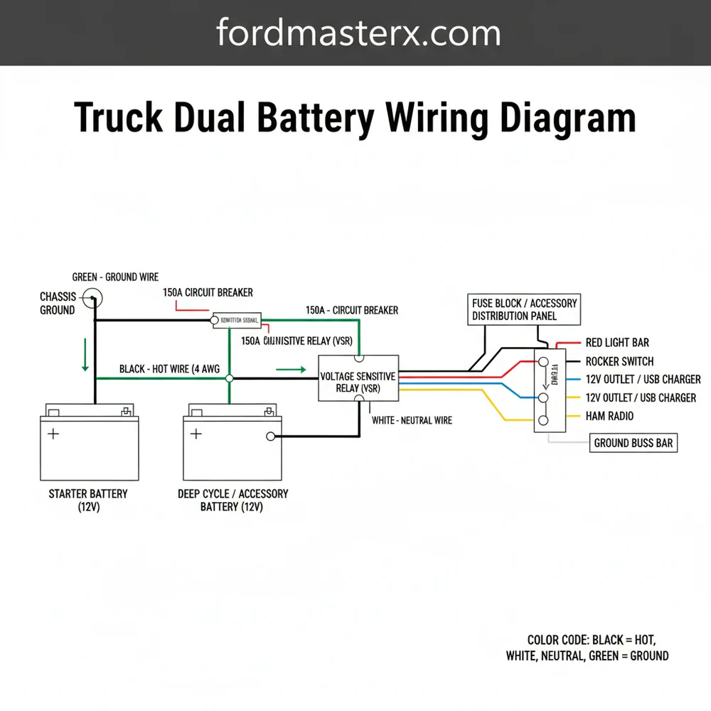
A comprehensive truck dual battery wiring diagram typically illustrates two distinct batteries connected via a smart isolator or a heavy-duty solenoid. The primary “starter” battery remains dedicated to the engine’s ignition system, while the secondary “house” battery handles auxiliary loads. The diagram identifies the hot wire—the main positive cable—running from the alternator to the common terminal of the isolator. From there, the current is distributed based on the state of the vehicle’s charging system.
In a dual battery setup, the “common terminal” on your isolator acts as the traffic controller. It senses the voltage levels of the starter battery and only allows current to flow to the auxiliary battery once the primary battery is sufficiently charged.
The visual components of the diagram include color-coded lines: red for the hot wire (positive) and black for the ground wire (negative). You will notice a traveler wire, often a smaller 14 or 16-gauge wire, that connects to an ignition-switched source. This ensures the solenoid only closes the circuit when the engine is running. The diagram also highlights the importance of the brass screw terminals found on most relays, which offer superior conductivity for the signal wires. Variations in these diagrams often depend on whether you use a manual marine-style switch, a basic solenoid, or a Voltage Sensitive Relay (VSR). High-output alternators may require a thicker gauge of wire to prevent overheating during high-amperage transfer cycles.
[ ALTERNATOR ] -------- (HOT WIRE) -------- [ STARTER BATTERY (+) ]
                                                |
                                                |
                                       [ FUSE / CIRCUIT BREAKER ]
                                                |
                                                |
                                       [ COMMON TERMINAL ]
                                       [ SMART ISOLATOR  ] -- (TRAVELER WIRE) -- [ IGNITION SWITCH ]
                                       [       OR        ]
                                       [    SOLENOID     ]
                                                |
                                                |
                                       [ FUSE / CIRCUIT BREAKER ]
                                                |
                                                |
[ CHASSIS GROUND ] ---- (GROUND WIRE) ---- [ AUXILIARY BATTERY (+) ]
                                                |
                                                |
[ ACCESSORIES ] <------- (VOLTAGE OUT) ---------|
Implementing the truck dual battery wiring diagram requires a methodical approach to ensure every connection is secure and logically placed. Follow these steps to complete your installation:
1. Battery Placement and Mounting: Begin by securing your auxiliary battery in a dedicated tray. Ensure it is placed away from extreme heat sources like exhaust manifolds. Both batteries must be firmly anchored to prevent vibration damage to the internal plates.
2. Grounding the System: Connect a heavy-gauge ground wire from the negative terminal of the auxiliary battery directly to the truck's chassis. In a DC system, the chassis acts as the neutral wire or return path. Use a wire brush to clear paint and rust from the connection point to ensure a metal-to-metal contact.
3. Installing the Isolator: Mount your isolator or solenoid between the two batteries. Identify the common terminal—this is where the power from the alternator or the primary battery enters the device. Use high-quality lugs and ensure the brass screw on the signal terminal is tightened to the manufacturer's torque specifications.
4. Running the Hot Wire: Measure the distance between the batteries and the isolator. Select a wire gauge appropriate for the distance and the alternator's amperage. A common choice is 2-gauge or 4-gauge copper wire. Run the red hot wire from the starter battery positive terminal to the isolator input, and then from the isolator output to the auxiliary battery positive terminal.
5. Integrating the Traveler Wire: If using a solenoid, connect the traveler wire from a "Key-On" power source in your fuse box to the small trigger terminal on the solenoid. This ensures that the two batteries are only linked when the alternator is spinning, preventing the house loads from draining the starter battery.
6. Circuit Protection: Install an appropriately rated fuse or circuit breaker on the hot wire within 12 inches of each battery terminal. This protects the system from catastrophic failure in the event of a short circuit along the main power run.
7. Final Voltage Check: Use a multimeter to check the voltage at both batteries. With the engine off, they should read independently. With the engine running, the voltage should rise on both batteries as the isolator engages and allows the alternator to charge the entire bank.
Never attempt to wire batteries in parallel without an isolator or manual switch. If the batteries are of different ages or types (e.g., Lead Acid and AGM), they will constantly discharge into one another, leading to premature battery failure or potential fire hazards.
Even with a perfect truck dual battery wiring diagram, issues can arise during the installation or over months of use. One of the most common problems is a significant voltage drop between the front and rear batteries. This is usually caused by using an insufficient wire gauge or having poor ground connections. If your auxiliary battery isn't charging, check the traveler wire to ensure it is receiving a 12V signal when the ignition is on.
Another frequent issue involves the isolator "chattering." This occurs when the voltage threshold is right on the edge of the engagement limit. It often indicates that the starter battery is weak or the alternator is struggling to keep up with the load. Inspect the brass screw terminals for signs of corrosion or arcing, as these can create resistance that mimics a failing battery. If you notice a "neutral wire" or ground wire getting hot to the touch, you likely have a short or an undersized cable that cannot handle the current flow.
- ✓ Check all connections for tightness and signs of heat discoloration.
- ✓ Verify that the circuit breakers haven't tripped due to a surge.
- ✓ Ensure the alternator output matches the total demand of both batteries.
To get the most out of your dual battery setup, prioritize high-quality components. While it may be tempting to save money on thinner cables, using the correct gauge is the single most important factor for safety and efficiency. For most truck applications, 4-gauge wire is the minimum recommended size for runs under 10 feet, while 2-gauge or 1/0-gauge is better for longer distances or high-amperage systems.
Use adhesive-lined heat shrink tubing on all terminal lugs. This prevents moisture from entering the wire strands, which is the primary cause of internal "green" corrosion that can destroy your wiring over time.
Maintenance is also key. Every six months, inspect the hot wire and ground wire for any signs of fraying or rubbing against the chassis. Apply a small amount of dielectric grease to the common terminal and battery posts to inhibit oxidation. If your truck sits for long periods, consider adding a trickle charger that can maintain both batteries through the isolator. By following a structured truck dual battery wiring diagram and adhering to these best practices, you create a reliable power ecosystem that supports your adventures and work needs without compromising your vehicle’s ability to start every single time. Consistent monitoring of your system's voltage will help you catch small issues before they become expensive repairs.
Step-by-Step Guide to Understanding the Truck Dual Battery Wiring Diagram: Easy Setup Guide
Identify - Start with identifying the ideal mounting location for the auxiliary battery and the isolator solenoid.
Locate - Locate the primary battery's positive terminal and the chassis ground point to prepare the hot wire routing.
Understand - Understand how the isolator acts as a common terminal to bridge the alternator current between both batteries.
Connect - Connect the ground wire from the negative terminal of the auxiliary battery to a clean, unpainted chassis point.
Verify - Verify that the traveler wire or ignition signal correctly triggers the solenoid to allow charging during engine operation.
Complete - Complete the circuit by ensuring the neutral wire equivalent connections are tight and testing the voltage at both batteries.
Frequently Asked Questions
Where is the auxiliary battery located?
In most trucks, the auxiliary battery is located in the engine bay on the opposite side of the primary battery or within the truck bed. Space constraints often dictate placement, but it must be securely mounted in a battery tray to prevent movement and vibration damage while driving.
What does a truck dual battery wiring diagram show?
This diagram shows the routing of the hot wire between two batteries and the integration of an isolator. It visualizes how the alternator charges both units and how the ground wire completes the circuit to the chassis, ensuring the secondary battery powers accessories independently of the starter.
How many connections does a battery isolator have?
A standard solenoid or isolator typically has four connections. These include a common terminal for the ignition source, two large studs for the main power cables, and a small ground wire terminal. Some advanced setups might include a traveler wire concept to signal status to a remote dashboard switch.
What are the symptoms of a bad dual battery setup?
Symptoms include the auxiliary battery failing to charge, accessories losing power quickly, or the primary battery draining unexpectedly. This often stems from a faulty isolator, a loose ground wire, or a blown fuse on the hot wire, preventing the alternator from distributing current to both batteries properly.
Can I install a dual battery system myself?
Yes, you can install this system if you have basic electrical knowledge and the right tools. By following a truck dual battery wiring diagram, you can safely route the hot wire and secure the ground wire. Ensure all connections are crimped tightly to prevent voltage drops or heat.
What tools do I need for this installation?
You will need a heavy-duty wire crimper, wire strippers, a socket set for battery terminals, and a multimeter. Additionally, you should have heat shrink tubing to protect connections and a drill to mount the battery tray and isolator securely within the vehicle’s engine compartment or bed.