Rear Drum Brake Assembly Diagram: Step-by-Step Instructions
A rear drum brake assembly diagram illustrates the complex arrangement of brake shoes, return springs, the wheel cylinder, and the self-adjusting mechanism inside the brake drum. It serves as a visual map for correctly positioning hardware, ensuring that hydraulic pressure translates into effective friction for reliable vehicle stopping power.
📌 Key Takeaways
- Provides a visual reference for the intricate placement of springs and adjusters
- Identifies the wheel cylinder as the primary hydraulic actuator
- Always use jack stands and eye protection when working on pressurized systems
- Take photos before disassembly to supplement the diagram for hardware orientation
- Use this diagram when replacing worn brake shoes or leaking wheel cylinders
Understanding your vehicle’s stopping power starts with a clear rear drum brake assembly diagram. Whether you are performing a routine inspection or a full overhaul, having a visual map is essential for safety and accuracy. This guide provides a detailed breakdown of every spring, pin, and lever within the system, ensuring you can navigate the complexities of drum hardware. You will learn how to identify components, interpret complex schematics, and apply this knowledge to practical repairs. By the end of this article, you will have the confidence to manage your rear drum brakes effectively.
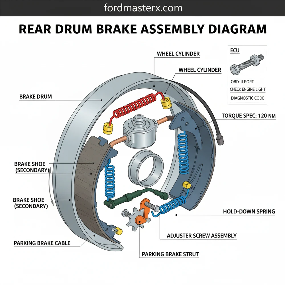
A rear drum brake assembly diagram serves as a blueprint for the mechanical friction system located on the rear axle of many trucks and economy cars. At the center of this system is the backing plate, a heavy-gauge steel disc that bolts directly to the axle housing. This plate acts as the foundation for all other components. Mounted at the top is the wheel cylinder, which receives hydraulic pressure from the master cylinder. When you press the brake pedal, the wheel cylinder’s pistons push outward against the two primary components: the brake shoes. These crescent-shaped metal frames are lined with high-friction material designed to press against the inner surface of the brake drum.
The diagram further illustrates a complex network of springs and levers. The return springs are usually color-coded—often blue, red, or green—to signify their specific tension and placement. These springs pull the shoes back to their resting position once the pedal is released. At the bottom of the assembly, you will find the self-adjuster mechanism, often referred to as a “star wheel.” This component ensures that the gap between the shoe and the drum remains consistent as the friction material wears down over time. In modern vehicles, while the drum system is largely mechanical, it often integrates with electronic systems. For instance, wheel speed sensors located near the backing plate send data to the ECU (Electronic Control Unit). If a sensor fails or the mechanical components bind, it may trigger a check engine light or an ABS warning, necessitating an OBD-II scan to retrieve a specific diagnostic code.
[DIAGRAM_PLACEHOLDER: A detailed 3D exploded view of a rear drum brake assembly. Labels include: 1. Brake Drum, 2. Primary Shoe, 3. Secondary Shoe, 4. Wheel Cylinder, 5. Return Springs, 6. Hold-down Pins, 7. Star Wheel Adjuster, 8. Parking Brake Lever, 9. Backing Plate.]
Reading a rear drum brake assembly diagram requires a systematic approach, as the mirror-image nature of the left and right sides of the vehicle can often lead to confusion. Follow these steps to interpret the diagram and apply it to your repair project:
- Orient the Backing Plate: Start by identifying the top and bottom of the diagram. The wheel cylinder is almost always at the 12 o’clock position, while the adjuster mechanism sits at the 6 o’clock position. Ensure the diagram matches the side of the vehicle you are working on, as the parking brake lever is usually offset toward the rear of the car.
- Identify Shoe Orientation: Notice in the diagram that the primary and secondary shoes are often different sizes. The primary shoe, which has a shorter friction lining, faces the front of the vehicle. The secondary shoe, with the longer lining, faces the rear. Installing these backward can lead to uneven wear and poor braking performance.
- Map the Spring Path: Use the diagram to trace where each spring hooks. Return springs typically connect the top of the shoes to a central anchor pin. The hold-down springs, which look like small coils with metal caps, secure the shoes to the backing plate via pins that pass through from the rear.
- Locate the Parking Brake Linkage: The diagram will show a mechanical lever attached to the secondary shoe. This lever connects to the parking brake cable. It is vital to ensure the “strut” or spreader bar is seated correctly between the two shoes as shown in the schematic.
- Verify the Adjuster Placement: The star wheel adjuster must be installed in the correct direction. Most diagrams indicate which way the teeth should face so that the adjuster lever can engage them properly when the vehicle reverses or the parking brake is applied.
- Apply Final Torque Specs: Once the assembly is complete, refer to your vehicle-specific manual for the correct torque spec for the hub nut and the lug nuts. Using a torque wrench ensures the drum and wheel are seated securely without warping the metal.
Always take a digital photograph of your brake assembly before removing any springs. While a rear drum brake assembly diagram is a perfect theoretical guide, your specific vehicle may have minor variations or previous aftermarket modifications that a photo will capture more accurately than a generic schematic.
Drum brakes are prone to several common issues that can be diagnosed using the assembly diagram. One frequent problem is “brake fade” or a “spongy” pedal feel. By looking at the diagram, you can trace this to a leaking wheel cylinder or air in the lines. If you notice a scraping or squealing sound, use the diagram to identify the location of the wear indicators on the shoes. Often, a “frozen” star wheel adjuster is the culprit for a low brake pedal; the diagram shows how the lever and wheel should interact, allowing you to see if the parts are seized by rust or debris.
Brake dust in older vehicles may contain asbestos. Never use compressed air to blow out a drum brake assembly. Instead, use a specialized brake cleaning solvent to dampen and wash away dust into a catch pan to avoid inhalation risks.
If your vehicle exhibits a check engine light alongside braking issues, it may not be the brakes themselves but a related sensor. Using an OBD-II scanner can provide a diagnostic code that points toward a wheel speed sensor failure. These sensors are often integrated into the backing plate shown on your diagram. If the code suggests an electrical fault, the issue might lie within the ECU’s processing of the signal rather than a mechanical failure of the shoes or drum.
To ensure a smooth repair, always work on one side of the vehicle at a time. This allows you to use the fully assembled side as a three-dimensional reference if you get confused by the 2D rear drum brake assembly diagram. Additionally, use a dedicated “brake spring tool” to remove and install the high-tension return springs. Attempting to use pliers often leads to slipped tools and hand injuries.
When replacing shoes, always use a small amount of high-temperature brake lubricant on the “bosses” or contact points of the backing plate where the metal shoes touch. This prevents “brake chatter” and ensures the shoes move smoothly during application.
While you have the vehicle jacked up and the wheels removed for brake work, it is a “best practice” to perform a general maintenance inspection. Check the condition of your accessory belt for cracks or fraying, as a failure here can lead to a loss of power steering and alternator function. Similarly, while the engine is cold, inspect the coolant flow by checking the radiator hoses for leaks or bulging. While the timing chain is usually an internal engine component not visible during a brake job, listening for any rattling sounds from the front of the engine while it is running can alert you to potential timing issues before they become catastrophic.
Maintaining your rear drum brakes is a critical aspect of vehicle ownership. By mastering the rear drum brake assembly diagram, you ensure that every component is installed to its specific torque spec, guaranteeing reliable performance. Regular cleaning and adjustment of the star wheel can extend the life of your brake shoes and keep your parking brake holding firmly on steep inclines. If you encounter complex electrical warnings, remember that your car’s ECU and OBD-II system are there to help narrow down the problem. With the right tools and a clear diagram, you can maintain your vehicle’s safety and save significantly on professional labor costs.
- ✓ Replace brake hardware (springs and pins) every time you change the shoes.
- ✓ Clean the backing plate thoroughly with a wire brush before installing new parts.
- ✓ Ensure the brake drum is within its maximum diameter specification, usually stamped on the drum itself.
- ✓ Bleed the brake lines if you have replaced the wheel cylinder to remove trapped air.
Frequently Asked Questions
Where is the rear drum brake assembly located?
The rear drum brake assembly is located behind the rear wheels, bolted to the axle flange or spindle. It is encased within a heavy metal drum that rotates with the wheel. To see the components, you must remove the wheel and pull the drum off the hub assembly.
What does a rear drum brake assembly diagram show?
The diagram shows the interaction between the primary and secondary brake shoes, the wheel cylinder, and the various return and hold-down springs. It highlights how the adjuster screw maintains the gap between the shoes and the drum, ensuring the system remains responsive as the brake friction material wears down.
How many connections does the brake assembly have?
The assembly features one main hydraulic connection to the brake line at the wheel cylinder and a mechanical connection to the parking brake cable. Additionally, modern vehicles may have an ABS speed sensor nearby that sends data to the ECU to prevent wheel lockup during hard braking events.
What are the symptoms of a bad rear drum brake?
Common symptoms include scraping noises, a low brake pedal, or the parking brake failing to hold. While these mechanical issues rarely trigger a check engine light, a faulty ABS sensor in the vicinity can store a diagnostic code in the ECU, which is retrievable via an OBD-II scanner.
Can I replace rear drum brakes myself?
Yes, you can replace them yourself using a diagram and the right tools. It is a moderately difficult DIY task because of the high-tension springs. Always work on one side at a time so you have the other side as a completed reference if you get confused.
What tools do I need for drum brake repair?
You will need a floor jack, jack stands, a lug wrench, and specialized drum brake spring pliers. A flathead screwdriver is useful for the adjuster, and a torque wrench is essential to ensure the wheel lugs and cylinder bolts meet the manufacturer’s required torque spec.