Hydroboost 7.3 Power Steering Hose Diagram: Setup Guide
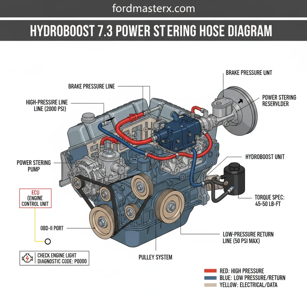
The hydroboost 7.3 power steering hose diagram illustrates the routing from the power steering pump to the hydroboost unit, then to the steering gear. It features a high-pressure line from the pump to the booster, another from the booster to the gear, and low-pressure return lines merging back at the reservoir.
📌 Key Takeaways
- Visualizing high-pressure fluid flow between the pump, booster, and gear
- Identifying the high-pressure lines versus low-pressure return lines
- Applying the correct torque spec to flare fittings to prevent leaks
- Using an OBD-II scanner to check for secondary codes if sensors trip
- When to use this diagram for 7.3L Powerstroke maintenance or conversions
When you are working on a heavy-duty truck like the Ford 7.3L Powerstroke, understanding the hydraulic layout of your braking and steering systems is paramount. Unlike standard vacuum-boosted brakes, the 7.3 utilizes a hydroboost system that leverages the power steering pump to provide assist for both steering and braking. Navigating a hydroboost 7.3 power steering hose diagram allows you to identify critical high-pressure lines and return paths that are essential for vehicle safety. In this guide, you will learn how to identify each component, interpret the flow of hydraulic fluid, and perform a successful hose replacement to ensure your truck remains responsive on the road.
Understanding the Hydroboost 7.3 Power Steering Hose Layout
The hydroboost system is a clever piece of engineering that replaces the bulky vacuum canister found in smaller vehicles. In a 7.3L diesel engine, which naturally produces very little vacuum, this system is a necessity. The diagram typically displays four primary hoses connecting three major components: the power steering pump, the hydroboost unit (mounted on the firewall), and the steering gear box. Understanding the distinction between high-pressure lines and low-pressure return lines is the first step in reading the diagram correctly.
The first line in the sequence is the high-pressure supply line that runs from the power steering pump directly to the hydroboost unit. This hose is often the most reinforced because it carries the initial surge of pressure required to actuate the brakes. From the hydroboost unit, a second high-pressure hose carries fluid down to the steering gear box. This “daisy-chain” configuration ensures that the braking system gets priority for hydraulic pressure. Finally, there are the return lines. One low-pressure hose returns fluid from the steering gear back to the reservoir, while a separate return line comes from the hydroboost unit. These often meet at a “T” fitting before entering the pump reservoir to complete the circuit.
Most 7.3 Powerstroke diagrams will show a specialized cooler located in front of the radiator. The power steering fluid passes through this cooler to maintain viscosity, preventing the pump from overheating during heavy towing or frequent braking.
Variations in the diagram may occur depending on the specific vehicle model, such as an F-250 versus an F-550 or an Excursion. While the routing remains largely identical, the length and bends of the hoses can vary significantly. Some diagrams may also include the power steering pressure switch, which communicates with the ECU to bump up engine RPM when the steering wheel is turned at a stop, preventing the engine from stalling under the heavy load of the pump.
How to Interpret and Use the Diagram for Repairs

Reading a hydroboost 7.3 power steering hose diagram requires an understanding of fluid dynamics. When you look at the visual representation, the arrows generally indicate the direction of fluid flow. If you are experiencing a loss of power assist in both your brakes and your steering, the diagram helps you trace the fault back to the common denominator—usually the pump or the primary pressure line. Follow these steps to translate the diagram into a physical repair on your truck:
- ✓ Step 1: Identify the Pump Outlet – Locating the starting point on your diagram, find the high-pressure port on the power steering pump. This is usually a threaded fitting located on the rear or side of the pump housing.
- ✓ Step 2: Trace the Primary Pressure Hose – Follow the line on the diagram from the pump to the hydroboost unit. On the truck, this hose runs along the driver-side inner fender and connects to the port closest to the driver on the hydroboost unit.
- ✓ Step 3: Locate the Steering Gear Feed – The diagram shows a second high-pressure line exiting the hydroboost and heading down toward the frame rail. This connects to the “input” port on the steering gear box.
- ✓ Step 4: Map the Return Circuit – Identify the non-threaded, low-pressure hoses secured by clamps. One leads from the steering gear back to the reservoir, and one leads from the hydroboost back to the reservoir.
- ✓ Step 5: Verify the Cooling Loop – Many 7.3 diagrams include the auxiliary cooler. Ensure the return line from the steering gear passes through this cooler before returning to the pump to aid in coolant flow and heat dissipation.
- ✓ Step 6: Check for Interference – While interpreting the diagram, check your physical engine bay for the accessory belt. Ensure no hoses are rubbing against the belt or the pulley system.
Hydraulic systems operate under extreme pressure. Never attempt to disconnect a hose while the engine is running or immediately after shutdown. Pump the brake pedal 20-40 times with the engine off to discharge the hydroboost accumulator before beginning work.
When performing the installation, tools such as flare nut wrenches (also known as line wrenches) are mandatory. Using a standard open-ended wrench on these fittings often results in rounded nuts. Furthermore, every fitting has a specific torque spec. Over-tightening can crack the aluminum housings of the hydroboost or steering gear, while under-tightening leads to persistent leaks. Consult your vehicle’s service manual for the exact foot-pounds required for each high-pressure fitting.
Common Issues and Troubleshooting with the Hydroboost System

The complexity of the hydroboost system means that a failure in one area can manifest in multiple ways. A common issue is a “spongy” brake pedal combined with “whining” from the power steering pump. By referencing the hose diagram, you can often pinpoint leaks at the O-ring seals where the high-pressure lines enter the components. If you notice fluid dripping from the bottom of the steering column inside the cab, the diagram helps you see that the internal seals of the hydroboost unit itself have likely failed, allowing fluid to bypass the piston.
Another frequent problem involves air getting trapped in the lines. This often occurs after a hose replacement. If the system isn’t bled correctly, you might see a check engine light or feel a vibration in the steering wheel. While the hydroboost itself is mechanical, modern diagnostic tools can sometimes read a diagnostic code through the OBD-II port if the vehicle is equipped with a steering pressure sensor that detects an imbalance. If your steering is stiff only when braking, the diagram points to a restriction in the line between the hydroboost unit and the steering gear.
If you are experiencing a “kickback” in the brake pedal, it is almost always caused by air in the high-pressure lines. Jack up the front of the truck, and with the engine off, turn the wheel lock-to-lock 20 times to purge the air manually before starting the engine.
Maintenance Tips and Best Practices
To keep your 7.3 Powerstroke’s hydroboost system functioning perfectly, regular maintenance is key. Unlike many components on this engine that are gear-driven (note that the 7.3 uses a gear-driven timing set rather than a timing chain), the power steering pump is driven by the accessory belt. Keeping this belt at the correct tension and free of cracks is the first step in ensuring the pump has the power it needs to feed the hydroboost system.
Fluid quality is the lifeblood of this system. Most 7.3 enthusiasts recommend using a high-quality synthetic ATF (Automatic Transmission Fluid) like Mercon V rather than standard “power steering fluid” found at generic shops. Synthetic fluids handle the heat generated by the hydroboost system much better, preventing the “baking” of the internal seals. When replacing hoses, always use new Teflon O-rings. These small rings are often forgotten but are the primary defense against high-pressure leaks at the connection points shown on your hydroboost 7.3 power steering hose diagram.
Finally, consider the age of your hoses. If your truck is several decades old, the internal lining of the rubber hoses can begin to degrade. These small bits of rubber can travel through the system and clog the narrow valves inside the hydroboost unit or the steering gear. Replacing all hoses as a set is often more cost-effective and provides better peace of mind than replacing them one by one as they fail. By following the diagram and maintaining high standards for parts and fluid, you ensure that your 7.3 Powerstroke remains a reliable workhorse for years to come.
In summary, mastering the hydroboost 7.3 power steering hose diagram is about more than just knowing where the lines go. It is about understanding the synergy between your braking and steering systems. Whether you are troubleshooting a diagnostic code or simply performing routine maintenance on your accessory belt and hydraulic lines, a clear understanding of this layout is your best tool for success. Always remember to double-check your torque spec and keep your fluid clean to avoid the common pitfalls of this robust hydraulic system.
Step-by-Step Guide to Understanding the Hydroboost 7.3 Power Steering Hose Diagram: Setup Guide
Identify the high-pressure supply port on the power steering pump and its connection to the hydroboost unit.
Locate the secondary pressure hose that travels from the hydroboost unit down to the steering gear box input.
Understand how the return lines from the steering gear and the hydroboost unit merge at the T-fitting or reservoir.
Connect the new hoses carefully, ensuring the O-rings are seated and fittings meet the manufacturer torque spec.
Verify that the ECU isn’t reporting any low-pressure warnings and that the check engine light remains off.
Complete the installation by filling the system with fluid and bleeding air by cycling the steering wheel.
Frequently Asked Questions
Where is the hydroboost unit located?
The hydroboost unit is located on the driver-side firewall, mounted directly between the brake pedal assembly and the master cylinder. It utilizes hydraulic pressure from the power steering pump to provide brake assist, making it a critical component for heavy-duty stopping power on the 7.3L diesel platform.
What does this diagram show?
This diagram provides a detailed map of the hydraulic circuit, including the high-pressure feed from the pump to the hydroboost, the pressure line from the hydroboost to the steering box, and the dual-return line configuration that sends fluid back to the power steering reservoir for cooling.
How many connections does the hydroboost unit have?
A standard 7.3 hydroboost unit has three main connections: one high-pressure inlet port from the power steering pump, one high-pressure outlet port leading to the steering gear box, and one low-pressure return nipple that connects to the reservoir via a rubber return hose and clamp.
What are the symptoms of a bad power steering hose?
Symptoms include fluid leaks at the hose crimps, a stiff or ‘hard’ brake pedal, and groaning noises when turning. While a leak won’t usually throw a specific diagnostic code, extreme fluid loss can trigger the check engine light or brake warning light on the dashboard.
Can I replace these hoses myself?
Yes, replacing these hoses is a common DIY task. After installation, you should use an OBD-II tool to ensure no related sensors are triggered. The process involves draining the fluid, swapping the lines, and performing a lock-to-lock air bleed procedure to restore full steering and braking function.
What tools do I need for this task?
You will need flare nut wrenches (typically 16mm and 18mm), a drain pan, and fresh ATF or power steering fluid. A torque wrench is vital to reach the exact torque spec for the high-pressure fittings to ensure they do not vibrate loose or strip the threads.