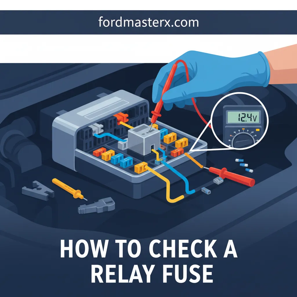
How To Check A Relay Fuse: A Technical Guide To Electrical Diagnostic Testing
A sudden failure in your vehicle’s fuel pump, cooling fan, or starter often points to a single, inexpensive component: the relay or its associated fuse. Diagnosing these electrical components can be frustrating for those who lack a structured testing methodology, leading to unnecessary parts replacement and diagnostic errors. In this guide, you will master the professional techniques required to accurately check a relay and its fuse using a multimeter, ensuring you can isolate electrical faults with precision. Whether you are a dedicated DIYer or an entry-level technician, this comprehensive walkthrough will help you understand the nuances of electrical diagnostic testing.
Understand Relay and Fuse Architecture in Automotive and Industrial Systems

📤 Share Image
To explore electrical troubleshooting effectively, one must first master the distinction between a fuse and a relay. A fuse is a sacrificial overcurrent protection device designed to fail when current exceeds a specific threshold, preventing harness fires. A relay, conversely, is an electromagnetic switch that allows a low-current control signal to manage a high-current load. When you “check a relay fuse,” you are often looking at two distinct parts of the same system: the fuse that protects the high-current path and the relay that switches it.
Most modern systems utilize the DIN 72552 numbering system. In a standard four or five-pin relay, pins 85 and 86 represent the coil (control side), while pins 30, 87, and 87a represent the contacts (load side). When power flows through the coil, it creates a magnetic field that physically pulls a movable armature to close the gap between pins 30 and 87. Understanding this mechanical action is essential because failure can occur either electrically (a burnt coil) or mechanically (pitted or stuck contacts).
By The Numbers: Relay Specifications
Operating Voltage Range
Standard Coil Resistance
Target Contact Resistance
Analyzing circuit diagrams allows you to discover the dual-fuse architecture common in complex machinery. For example, a typical fuel pump relay circuit utilizes a 20A “Maxi” fuse to provide primary power to pin 30 (the load), while a separate 5A mini-fuse protects the Powertrain Control Module (PCM) signal that triggers pin 86. If the 20A fuse is blown, the relay may “click” perfectly, but the pump will never receive power. Conversely, if the 5A fuse fails, the relay will remain silent regardless of the pump’s health.

Prepare the Diagnostic Environment and Essential Testing Apparatus
Before diving into testing, you must ensure your instrumentation is capable of providing accurate data. A high-quality Digital Multimeter (DMM) is non-negotiable. I recommend a meter like the Fluke 87V, which offers high impedance to prevent “ghost voltage” readings—a common pitfall where a circuit appears to have voltage but cannot support a load. Your DMM should have a resolution of at least 0.1 ohms to master the detection of high-resistance contacts.
Before blaming a relay, ensure the battery is at a stable state of charge (minimum 12.6V). Corroded terminals can increase circuit resistance by as much as 2.0 ohms, which is enough to cause a 10% voltage drop in a 12V system, potentially preventing the relay from “pulling in” even if it’s functional.
Locate the Power Distribution Center (PDC) and use the diagram on the underside of the lid to discover the exact location of the relay and its corresponding fuse. It is also wise to utilize fused jumper wires or a 12V power probe for bench testing. This allows you to safely energize the relay coil without the risk of an accidental short circuit damaging the vehicle’s computer. Always inspect the relay socket for signs of thermal stress. Melted plastic or discolored brass terminals are clear indicators of high resistance at the connection point, which no amount of relay replacement will fix.
Perform a Sequential Continuity Test on the Protective Fuse
The most common beginner mistake is skipping the fuse test and jumping straight to the relay. You must rule out the simplest failure point first. While a visual inspection can sometimes identify a blown fuse, it is notoriously unreliable. Master the use of your DMM in continuity mode (the “beep” setting) to verify physical integrity. However, for a more comprehensive analysis, an “In-Circuit” voltage test is superior.
📋
Step-by-Step Fuse Validation
Turn the ignition or machine switch to the ‘ON’ position so the fuse is receiving live power.
Touch the DMM leads to the two small metal test points on the top of the fuse. A good fuse will show 0V across these points because there is no resistance.
If you see 12V across the test points, the fuse is blown (open circuit). A reading higher than 100mV suggests high resistance.
Consider a scenario where a visual inspection shows a clear fuse, but a voltage drop test reveals a hairline fracture in the element that only opens when the circuit attempts to pull current. This is why replacing a fuse with a higher amperage rating is a critical safety violation; it bypasses the protection and can lead to harness fires if the fault is a short to ground. Always identify why the fuse blew—was it an overcurrent from a seized cooling fan motor or a literal short in the wiring?
Test the Relay Coil and Contact Resistance Using a Multimeter
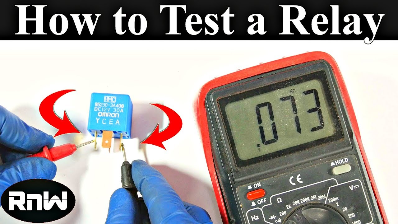
Once the fuse is confirmed good, move to the relay. Set your DMM to the resistance (Ohms) setting. First, measure the resistance across pins 85 and 86. This tests the integrity of the electromagnetic coil. An ‘OL’ (Open Loop) reading indicates a broken internal wire, meaning the relay is dead. Typically, a healthy automotive relay coil will measure between 50 and 120 ohms.
Some relays include an internal diode or resistor for suppression. If a diode-equipped relay is installed backward or tested with reversed polarity, the diode can fail, causing ‘flyback’ voltage spikes that can destroy sensitive ECU transistors. Always verify the diagram on the relay casing before applying power.
Next, test the Normally Open (NO) contacts. With the relay de-energized, probe pins 30 and 87; you should see infinite resistance (‘OL’). Now, energize the coil by applying 12V to pin 86 and ground to pin 85. You should hear a distinct ‘click.’ While energized, re-measure the resistance across pins 30 and 87. It must read less than 0.5 ohms. A reading of 3.5 ohms might seem “low,” but in a high-current circuit like an AC clutch, it creates enough of a voltage drop to prevent the compressor from engaging. This is known as “pitting” or carbon fouling of the internal contact surfaces.
✅ Optimal Readings
- Coil (85-86): 75 ohms
- De-energized (30-87): OL
- Energized (30-87): 0.2 ohms
- Voltage Drop: <100mV
❌ Failure Indicators
- Coil (85-86): <40 ohms (Short)
- Energized (30-87): >1.0 ohm
- No ‘Click’ at 9V+
- Discolored terminal pins
Execute Dynamic Bench Testing and Stress Analysis
The final frontier of testing is the dynamic stress analysis. Some relays pass a static continuity test when cold but develop an open circuit once they reach operating temperature. You can discover these intermittent “hot” failures by applying heat to the relay with a heat gun (staying within the 180°F operational limit) while cycling the coil. If the contact resistance climbs as the temperature rises, the relay is failing and must be replaced.
To master this process, perform a “loaded” voltage test. Instead of just checking for continuity, place a test light or a small 12V bulb across the output pins (30 and 87) while the relay is energized. If the bulb is dim, the contacts cannot carry the necessary current, even if your DMM showed low resistance. Relays are typically rated for 100,000 to 1,000,000 electrical cycles; however, the contact material (Silver Tin Oxide vs. Silver Nickel) significantly impacts this longevity in high-heat environments like an engine bay.
Relay Swapping
If two relays share the same part number (e.g., Horn and AC), swap them. If the fault moves, the relay is the culprit. Quick and definitive.
Millisecond Timing
Specialized relay testers measure the ‘pull-in’ time. A slow relay can cause timing issues in computerized fuel systems.
Document your findings carefully. If the relay and fuse both pass these tests, you have effectively isolated the fault to the control circuit (the ECU or switch not sending the ground/power signal) or the load component itself (a burned-out motor or broken ground). This methodical exclusion is what separates a seasoned expert from a “parts-changer.”
In summary, to understand and master the process of checking a relay fuse, you must verify the protective fuse integrity before moving to complex relay diagnostics. Always use a Digital Multimeter to test both coil resistance and contact continuity under energized conditions. Look beyond simple “clicks” to measure actual resistance values that can indicate failing internal contacts. Before purchasing a replacement, perform these bench tests to ensure the relay is truly the culprit; if the relay passes, proceed to inspect the control circuit and ground connections for higher-level electrical faults.
Frequently Asked Questions
Can I test a relay without a multimeter?
While you can listen for an audible ‘click’ when the relay is energized or swap it with a known-good relay of the same type, these methods are not definitive. A relay can click but still fail to deliver power if the internal contacts are carbon-fouled or pitted. Only a multimeter can verify the low-resistance path required for high-current loads.
What does it mean if my relay is getting very hot?
Excessive heat in a relay is usually caused by high resistance across the internal contacts or a loose connection in the relay socket. If the contacts are pitted, they create a bottleneck for current, generating thermal energy. If the relay is too hot to touch, it should be replaced immediately, and the socket terminals should be inspected for tension and corrosion.
Why does my fuse keep blowing even after I replaced the relay?
Fuses blow due to overcurrent, usually caused by a short circuit to ground or a failing load component (like a motor with a shorted winding). If replacing the relay doesn’t solve the issue, the problem likely lies downstream in the wiring harness or the component the relay is powering. You must perform a parasitic draw or short-to-ground test.
What is the difference between a 4-pin and 5-pin relay?
A 4-pin relay is a Single Pole Single Throw (SPST) switch used to turn one circuit on or off. A 5-pin relay is a Single Pole Double Throw (SPDT) switch that features an extra pin (87a). When the 5-pin relay is de-energized, power flows through pin 87a; when energized, it flips to pin 87, allowing for alternating between two circuits.
How do I know if the relay coil is bad?
To test the coil, set your multimeter to Ohms (Ω) and probe pins 85 and 86. A healthy coil usually shows a resistance between 50 and 120 ohms. If your meter reads ‘OL’ (Open Loop), the thin copper wire inside the coil has snapped, and the relay will never engage. A reading near zero indicates a shorted coil.