Gas Tank Ford F150 Fuel System Diagram: Diagnosis Guide
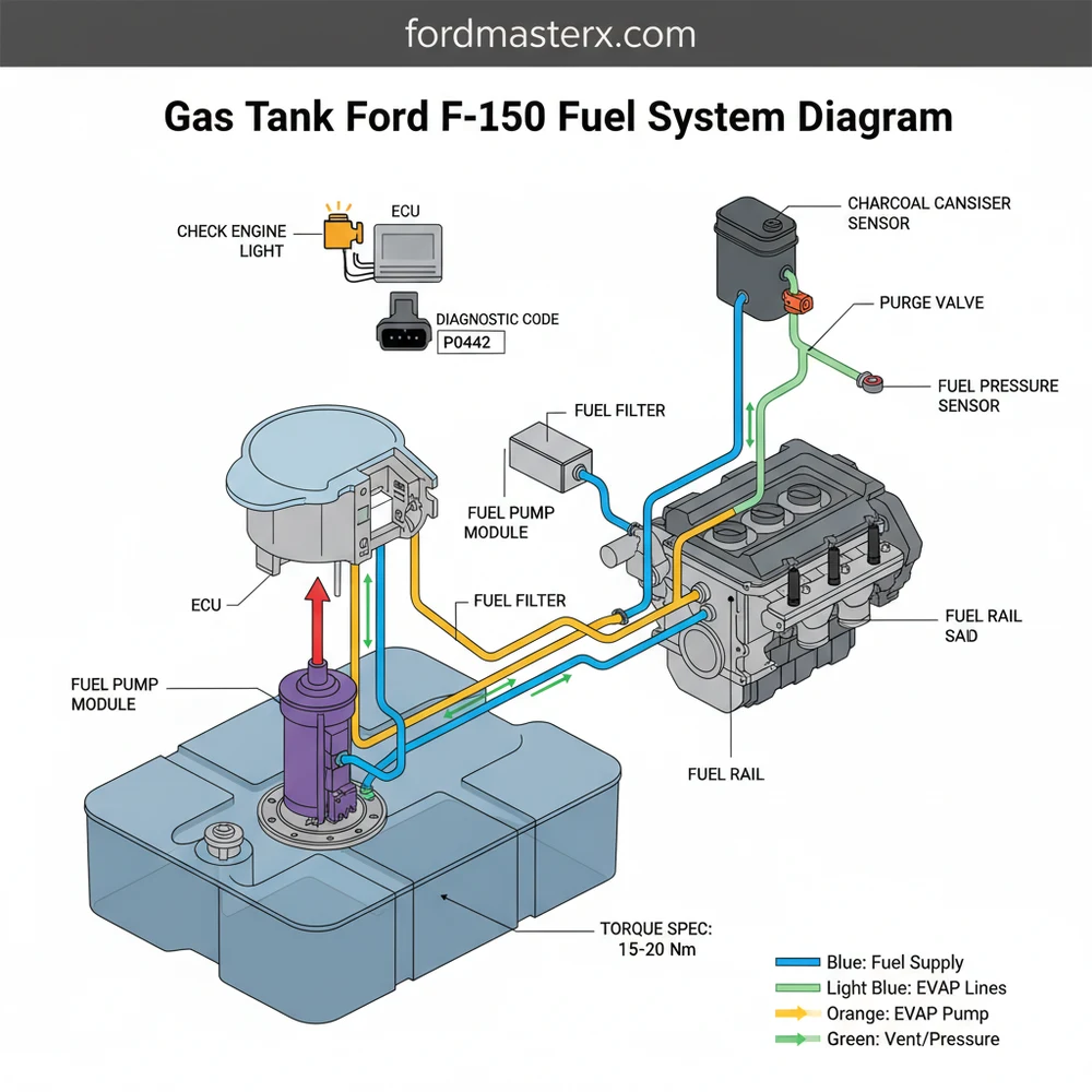
A gas tank Ford F150 fuel system diagram maps the flow of gasoline from the reservoir to the engine, highlighting the fuel pump assembly, sending unit, and EVAP lines. It is essential for locating the fuel filter and understanding how the ECU regulates fuel pressure to ensure optimal engine performance and efficiency.
📌 Key Takeaways
- Illustrates the complete fuel delivery path from tank to rail
- Identifies the fuel pump assembly as the primary pressure source
- Safety involves relieving system pressure before any disconnection
- Use the diagram to trace electrical connections to the fuel driver module
- Indispensable for diagnosing fuel delivery and EVAP leak codes
Understanding your vehicle’s fueling architecture is essential for any DIY mechanic or truck owner looking to maintain engine performance. A comprehensive gas tank ford f150 fuel system diagram serves as your primary roadmap for identifying leaks, replacing aging pumps, or diagnosing complex emissions codes. By studying the layout from the rear filler neck to the engine bay injectors, you gain the clarity needed to perform repairs safely and efficiently. This guide will walk you through every component, teaching you how to interpret technical schematics and troubleshoot common fuel-related failures using modern diagnostic tools.
The Ford F-150 fuel system is a high-pressure environment. Most modern fuel-injected models operate between 40 and 65 PSI. Always bleed the pressure at the Schrader valve on the fuel rail before disconnecting any lines identified in your diagram.
Decoding the Gas Tank Ford F150 Fuel System Diagram
The fuel system in a Ford F-150 is a sophisticated loop that balances pressure, filtration, and vapor management. When looking at a gas tank ford f150 fuel system diagram, the most prominent feature is the fuel tank itself, usually mounted mid-ship on the driver-side frame rail. Inside this tank sits the Fuel Pump Assembly, which is the heart of the system. This assembly includes the pump motor, a primary strainer, and the fuel level sending unit.
The diagram further illustrates the path of the fuel through the supply lines. In older models, you may see an external fuel filter mounted along the frame rail, while newer versions utilize a “lifetime” filter integrated into the pump assembly. The lines lead directly to the fuel rail, which distributes gasoline to the individual fuel injectors. Another critical aspect of the diagram is the EVAP (Evaporative Emission Control) system. This includes the charcoal canister and the purge valve, which prevent raw gasoline vapors from escaping into the atmosphere.
Variations in these diagrams occur based on wheelbase and engine type. A SuperCrew with a 6.5-foot bed will have a larger tank capacity and longer fuel lines than a Regular Cab model. Furthermore, if your truck features a Flex Fuel engine, the diagram may include a fuel composition sensor that communicates with the ECU to adjust timing and spray patterns based on ethanol content.
Step-by-Step Guide to Interpreting and Utilizing the Diagram
Navigating a fuel system schematic can feel overwhelming without a logical approach. Follow these steps to translate the lines and symbols into a successful repair or inspection.
1. Identify the Primary Components
Start at the rear of the diagram with the fuel filler neck and follow it to the gas tank. Locate the fuel pump mounting flange on top of the tank. This is where the electrical harness connects the pump to the vehicle’s ECU. Recognizing these landmarks helps you orient yourself when you are physically under the truck.
2. Trace the Supply and Return Paths
Modern F-150s often use a “returnless” fuel system, meaning there is only one supply line going to the engine. If your diagram shows two lines running parallel, you have a return-style system where excess fuel is sent back to the tank to stay cool. Trace these lines toward the engine bay, noting where they clip into the frame to avoid heat sources like the exhaust.
3. Locate the EVAP System Junctions
Look for the lines exiting the top of the tank that lead to a rectangular box; this is the charcoal canister. This subsystem is vital for passing emissions. The diagram will show a line running from this canister up to the intake manifold, where the purge valve resides.
4. Verify Electrical and Sensor Connections
The fuel system doesn’t operate in a vacuum. The diagram will highlight connections to the Fuel Pump Driver Module (FPDM). On many F-150 models, this module is located on a crossmember above the spare tire. It receives signals from the ECU to vary the pump speed, ensuring the engine receives exactly the right amount of fuel based on throttle position.
5. Prepare Necessary Tools and Safety Equipment
Before using the diagram for a physical repair, gather the following:
- ✓ Fuel line disconnect tool set (usually 3/8″ and 5/16″)
- ✓ Digital Multimeter for electrical testing
- ✓ Fuel pressure gauge
- ✓ Brass punch and hammer (for the fuel pump locking ring)
- ✓ Fire extinguisher and safety glasses
Gasoline is highly flammable. Work in a well-ventilated area and never use a shop light with an exposed incandescent bulb. A single drop of fuel on a hot bulb can cause an explosion.
Common Issues and Troubleshooting with the Diagram
When your truck begins to stumble, stall, or displays a check engine light, the fuel system diagram becomes a diagnostic treasure map. One of the most common issues is a failed Fuel Pump Driver Module, which often corrodes due to its location on the frame. If your truck cranks but won’t start, the diagram helps you locate this module to check for power and ground.
Another frequent problem is a localized leak or a clogged injector. By using an OBD-II scanner, you may find a diagnostic code such as P0171 or P0174 (System Too Lean). The diagram allows you to trace the fuel path to check for vacuum leaks in the EVAP lines or to locate the fuel pressure regulator. If the check engine light is flashing, it often indicates a severe misfire, which could be linked to a faulty injector identified on your engine-side schematic.
If you are experiencing a “tight” fueling experience where the pump clicks off repeatedly at the gas station, use your diagram to locate the EVAP vent solenoid. It is likely clogged with dust or spider webs, preventing the tank from venting during fill-ups.
Maintenance Best Practices and Pro Tips
To keep your fuel system in top condition, maintenance should extend beyond just the gas tank. While the fuel system provides the “juice,” it must work in harmony with the rest of the engine. For instance, ensure your accessory belt is in good condition, as it drives the alternator that provides the steady voltage required by the ECU and fuel pump. Similarly, maintaining the timing chain and ensuring proper coolant flow prevents engine overheating, which can lead to fuel vapor lock in extreme conditions.
When replacing components, always adhere to the specific torque spec for the fuel pump locking ring to ensure a vapor-tight seal. Using high-quality OEM parts is highly recommended, as the ECU is calibrated for the specific flow rates of factory injectors and pumps. Cheap aftermarket pumps often have incorrect resistance values, which can trigger a diagnostic code even if the pump is technically “working.”
Finally, try to avoid running your F-150 with less than a quarter tank of gas. The gasoline in the tank acts as a coolant for the fuel pump motor. Consistently running on “E” allows the pump to run hot, significantly shortening its lifespan. By following these best practices and keeping your gas tank ford f150 fuel system diagram handy, you ensure your truck remains reliable for hundreds of thousands of miles. Whether you are chasing a ghost in the electrical system or performing a standard filter change, the diagram is the most valuable tool in your arsenal.
Frequently Asked Questions
Where is the fuel pump located on a Ford F150?
The fuel pump is located inside the gas tank, typically accessed by lowering the tank or removing the truck bed. The diagram shows it sits in the top-center of the tank, integrated into a module that includes the fuel level sending unit and a primary strainer filter.
What does this fuel system diagram show?
This diagram displays the layout of the gas tank, fuel supply and return lines, the EVAP charcoal canister, and the fuel injectors. It helps users visualize the electrical path between the fuel pump driver module and the engine sensors for easier troubleshooting of delivery malfunctions.
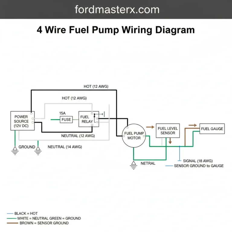
How many connections does the fuel pump assembly have?
The fuel pump assembly typically has one main electrical connector with four to six pins and two or three quick-connect fluid ports. These ports handle the high-pressure supply line, the return line on older models, and the vapor line leading to the emissions system for pressure regulation.
What are the symptoms of a bad F150 fuel system?
Common symptoms include engine sputtering at high speeds, difficulty starting, and a loss of power under load. You may also see a check engine light on the dashboard, which usually triggers a specific diagnostic code like P0191 or P0087 when scanned via an OBD-II tool.
Can I replace the gas tank myself?
Yes, replacing a gas tank is a feasible DIY task if you have a floor jack and basic hand tools. However, it is much easier when the tank is nearly empty. Always follow the diagram to ensure fuel and vapor lines are reconnected to their correct ports to avoid leaks.
What tools do I need for fuel system work?
You will need a set of fuel line disconnect tools, a socket set to remove tank straps, and an OBD-II scanner to clear codes. Most importantly, use a torque wrench to ensure the mounting strap bolts meet the manufacturer’s torque spec for safety and to prevent tank movement.