Fuel Pump Kill Switch Diagram: Easy Setup Guide
A fuel pump kill switch diagram illustrates how to wire an inline switch into the fuel pump’s power supply. It typically involves cutting the hot wire and routing it through a toggle switch. This setup ensures that unless the switch is engaged, the fuel pump remains inactive, effectively preventing the vehicle from starting.
📌 Key Takeaways
- The primary purpose is to provide an effective anti-theft solution.
- The most important component to identify is the fuel pump relay or power wire.
- Always use automotive-grade wire and proper insulation to prevent fire risks.
- Hide the switch in a location that is reachable but not visible to passengers.
- Use this diagram when adding a manual layer of security to your vehicle.
Installing an anti-theft device is a top priority for many vehicle owners looking to secure their investment against sophisticated car thieves. This comprehensive guide provides a detailed fuel pump kill switch diagram to help you understand how to safely interrupt the electrical circuit powering your engine’s fuel supply. By following this wiring layout, you will learn how to identify critical components, choose the correct wire gauge, and install a hidden toggle that prevents the engine from starting without your permission. Having the correct diagram is essential for maintaining electrical integrity and preventing accidental shorts or blown fuses.
Understanding the Fuel Pump Kill Switch Diagram
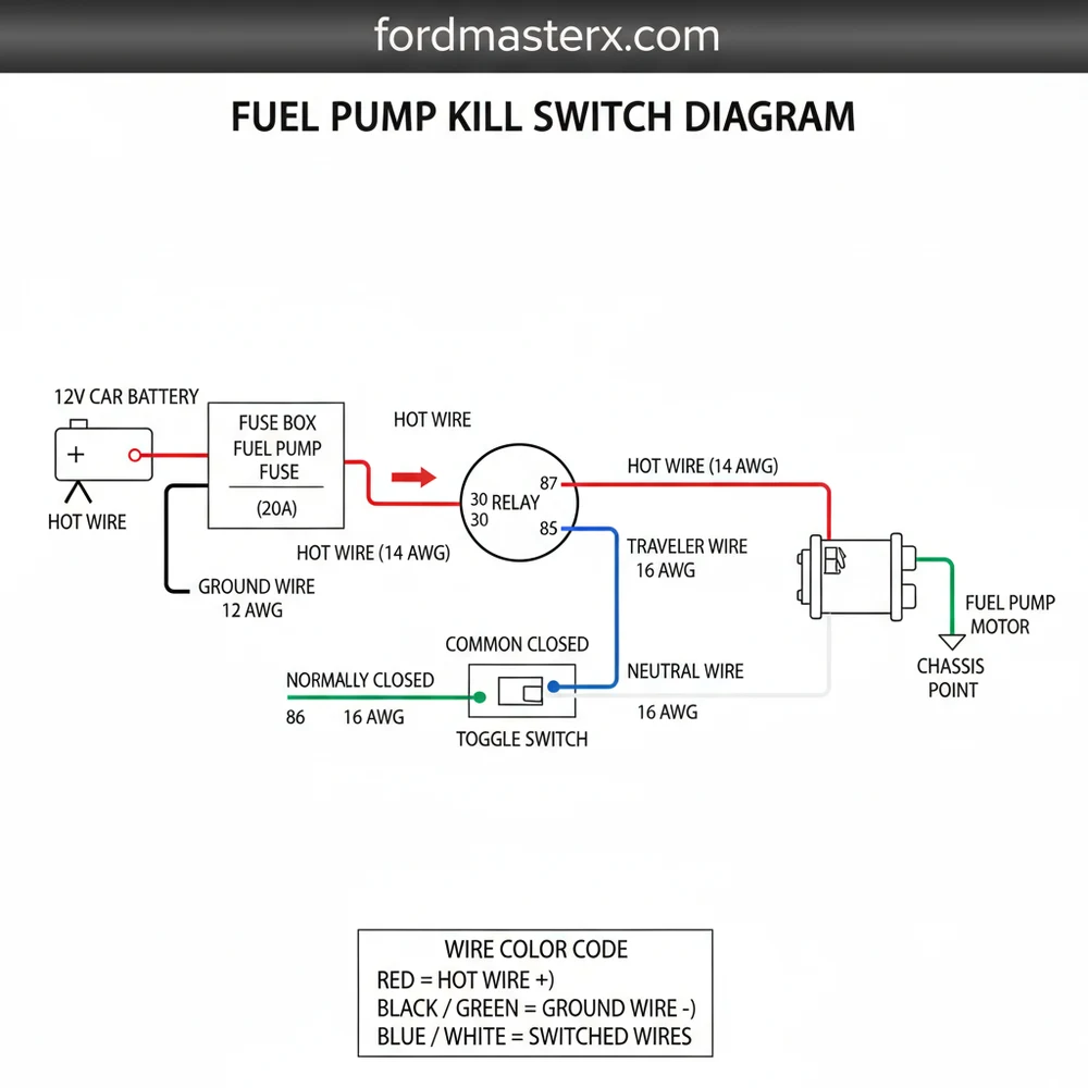
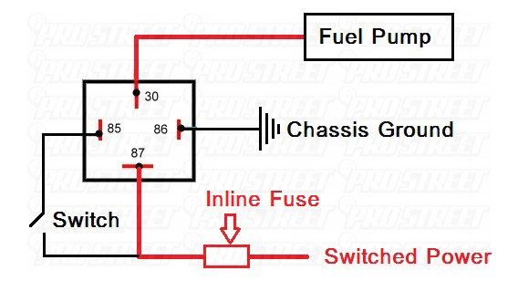
The fuel pump kill switch diagram illustrates a simple but effective interruption in the DC electrical circuit that powers your fuel pump. In a standard automotive setup, the fuel pump receives power from the battery via a fuse and a relay. The diagram shows how a manual toggle switch is placed in series along the hot wire, which is the positive lead running from the fuel pump relay to the pump itself. This creates a break in the circuit that must be physically closed by the switch for the pump to operate.
Key elements in the diagram include the power source, the relay, the switch terminals, and the ground wire connections. When you look at the diagram, you will notice the hot wire is typically color-coded to represent the positive current flow. If you are using a standard household-style toggle for a custom project, you might see references to a traveler wire or a common terminal; however, in automotive applications, we focus on the input and output of the switch. The diagram also highlights the importance of the ground wire, which provides the return path to the battery, completing the circuit. Even though “neutral wire” is a term more common in AC residential wiring, in the context of this diagram, it represents the return path or negative side of the DC loop.
Visualizing the diagram requires identifying the “load” side of the relay. This is where the switch is most effective. The diagram will often show a specific gauge of wire, usually 14 or 16 AWG, to ensure the circuit can handle the amperage required by the fuel pump without overheating.
Figure 1: Basic Series Interruption Wiring Layout
Step-by-Step Installation and Wiring Guide
Implementing a fuel pump kill switch diagram requires precision and a basic understanding of your vehicle’s electrical system. Before starting, ensure you have a digital multimeter to test for voltage and continuity.
Always disconnect the negative battery terminal before cutting any wires to prevent short circuits and potential damage to the vehicle’s Engine Control Unit (ECU).
1. Locate the Fuel Pump Wire
Consult your vehicle’s service manual to identify the hot wire leading to the fuel pump. This is often found along the driver’s side door sill or near the fuel pump relay in the engine bay fuse box. Use your multimeter to verify that this wire shows 12 volts only when the ignition is turned to the “on” position.
2. Select Your Switch and Location
Choose a high-quality toggle switch rated for at least 20 amps. Decide on a hidden location that is accessible from the driver’s seat but not visible to an intruder. Common locations include under the dashboard, inside the center console, or beneath the carpet.
3. Prepare the Wiring
Measure the distance from the wire you are tapping into to your switch location. Use the same gauge wire as the factory harness—typically 14 or 16 gauge. You will need two lengths of wire: one to act as the “input” from the power source and one to act as the “traveler wire” back to the fuel pump.
4. Cut and Strip the Factory Wire
Cut the identified fuel pump hot wire. Strip approximately half an inch of insulation from both ends. This is the point where you will insert your kill switch into the circuit loop.
5. Connect the Switch
If using a switch with screw terminals, wrap the stripped end of your new wire around the brass screw and tighten it firmly. If your switch uses spade connectors, crimp a female spade terminal onto your wires. Connect the input wire to the common terminal and the traveler wire to the accessory terminal of the switch.
Loose connections can cause heat buildup and melting. Always use heat-shrink tubing to insulate your connections and prevent them from touching the vehicle’s metal chassis.
6. Complete the Circuit
Run your new wires back to the factory wire you cut in step four. Use a butt connector or solder the joints to connect the input wire to the side coming from the relay, and the traveler wire to the side going to the fuel pump.
7. Test the Installation
Reconnect the battery. With the kill switch in the “off” position, try to start the car. The engine should crank but fail to fire because the fuel pump is not receiving voltage. Flip the switch to “on” and start the engine; it should run normally.
- ✓ Multimeter for testing voltage
- ✓ 14 or 16 AWG automotive-grade wire
- ✓ 20-Amp toggle switch
- ✓ Wire strippers and crimping tool
- ✓ Heat-shrink tubing and electrical tape
Common Issues and Troubleshooting
Even with a perfect fuel pump kill switch diagram, you may encounter issues during or after installation. The most common problem is a “no-start” condition even when the switch is in the “on” position. This is usually caused by a poor connection at the common terminal or the brass screw of the switch. Use your multimeter to check for voltage on both sides of the switch; if the input has power but the traveler wire doesn’t when the switch is closed, the switch itself may be faulty.
Another issue is a blown fuse. If the wire gauge you used is too thin, it may create resistance, leading to increased heat and a blown fuel pump fuse. Always match the gauge to the factory specifications. Additionally, ensure the ground wire of the fuel pump is undisturbed. While the kill switch interrupts the hot wire, a loose ground wire elsewhere in the system will cause the pump to fail intermittently. If the vehicle stalls while driving, check for loose crimps or vibrating wires that may be grounding out against the frame. If you cannot find the break in the circuit, it may be time to consult a professional automotive electrician to avoid damaging the vehicle’s computer.
Tips and Best Practices for a Reliable Kill Switch
To ensure your kill switch remains a reliable part of your vehicle’s security for years, follow these best practices. First, prioritize the quality of your components. Avoid cheap, plastic switches found in general hardware bins. Instead, opt for heavy-duty, marine-grade, or automotive-specific toggles that can withstand vibration and temperature fluctuations.
Solder your connections instead of using crimp-on butt connectors. Soldered joints are more resistant to the vibrations of a moving vehicle and provide better electrical conductivity with less voltage drop.
When routing your wires, avoid sharp metal edges or moving parts like the steering column or pedal assembly. Use plastic wire loom to protect the wires and make the installation look like a factory part of the harness. This not only protects the circuit but also makes it harder for a thief to identify the modification.
Maintenance is also key. Every few months, check the switch for signs of heat or melting and ensure the wires are still seated firmly on the terminals. If you live in a high-humidity area, a dab of dielectric grease on the brass screw connections can prevent corrosion. Finally, never tell anyone where your switch is located. The effectiveness of a fuel pump kill switch relies entirely on its secrecy. By following the fuel pump kill switch diagram accurately and using high-quality materials, you provide a robust layer of protection that can stop even the most determined car thief in their tracks.
Frequently Asked Questions
Where is the fuel pump kill switch located?
The kill switch is usually hidden under the dashboard, inside the center console, or beneath the carpet. Finding a discreet spot is vital for security, as it prevents unauthorized users from easily locating and bypassing the switch to start the engine, even if they have the keys.
What does a fuel pump kill switch diagram show?
The fuel pump kill switch diagram illustrates the electrical path from the power source to the pump. It shows where to safely splice into the hot wire to insert a switch, ensuring you understand the circuit flow and wire colors before making permanent modifications to your vehicle’s harness.
How many wires does a kill switch have?
A basic setup involves two main connections. You break the hot wire and connect each end to the switch terminals. In complex relay setups, a traveler wire may connect to a common terminal. Ensure the ground wire is secure, noting that automotive systems use ground rather than a neutral wire.
What are the symptoms of a bad kill switch?
A failing kill switch may cause the engine to crank but not start, or cause the vehicle to stall unexpectedly. If the switch or common terminal develops high resistance, the fuel pump may receive insufficient voltage, leading to poor engine performance, sputtering, or intermittent starting issues during operation.
Can I install this kill switch myself?
Yes, you can install this yourself if you have basic electrical knowledge. Using a fuel pump kill switch diagram makes the process straightforward. However, ensure you use proper wire gauges and secure crimp connectors to maintain circuit integrity and prevent potential electrical shorts or vehicle fire hazards.
What tools do I need for this task?
You will need a wire stripper, crimping tool, electrical tape or heat shrink tubing, and a multimeter. A soldering iron is recommended for the most secure connections. You also need the switch itself and extra automotive-grade wire to reach your chosen hidden mounting location inside the vehicle cabin.