Ford Super Duty Wheel Offset Chart & Bolt Pattern Guide (F-250/F-350/F-450)
The Ford Super Duty platform, a lineage that formally diverged from the light-duty F-150 architecture in 1999, stands as the preeminent heavy-duty towing and hauling consumer vehicle in the North American market. However, the engineering reality of these vehicles—spanning the F-250, F-350, and F-450—is far more complex than simple payload ratings.
The interface between the vehicle and the road is governed by precise wheel geometry, a system where the variables of offset, backspacing, bolt pattern, and hub bore diameter dictate not only aesthetic stance but fundamentally influence suspension longevity, steering dynamics, and operational safety.
For the automotive technician, the fleet manager, or the enthusiast owner, understanding these specifications is critical. The Super Duty has undergone radical suspension shifts—from the leaf-sprung front solid axles of the early 2000s to the massive, wide-track radius arm coil setups of the modern “Alumiduty” era. Each of these mechanical evolutions has necessitated specific changes in wheel offset to maintain the vehicle’s scrub radius and turning geometry.
A miscalculation in wheel selection, specifically the common error of applying aggressive negative offsets to a solid-axle truck without compensatory suspension modifications, acts as a primary catalyst for accelerated wear of ball joints, unit bearings, and the onset of the catastrophic oscillation known as “Death Wobble.”
This report serves as an exhaustive technical repository for Ford Super Duty wheel specifications from the platform’s inception in 1999 through the 2026 model year. It synthesizes data regarding the chassis codes—from the original PHN131 to the modern P708—analyzing the transition of bolt patterns, the bifurcation of F-450 pickup and chassis cab standards, and the granular fitment data required to accommodate 35-inch and 37-inch tires across varying suspension heights.
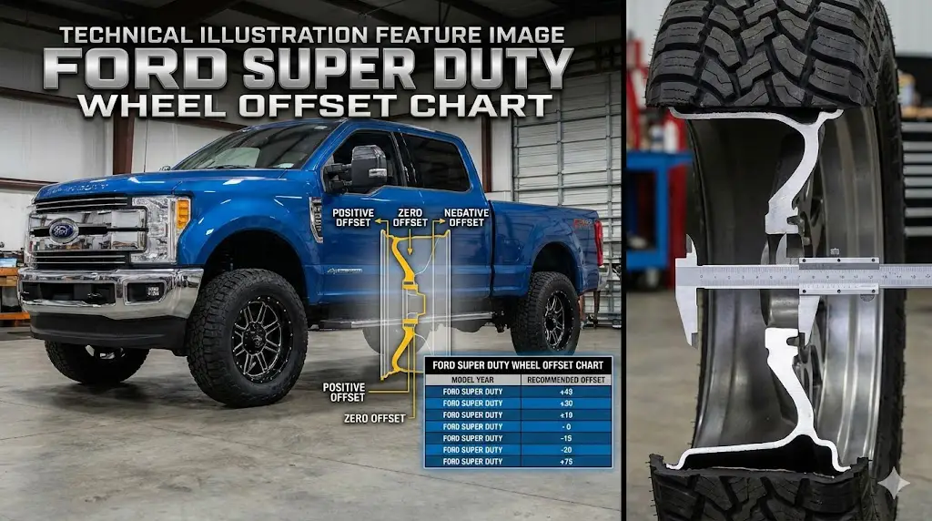
SUPER DUTY WHEEL OFFSET CHART
The ultimate guide to fitment, stance, and specs for Ford F-250 & F-350. Stop rubbing and start styling.
1 Understanding the Golden Numbers
Before diving into custom stances, every Super Duty owner needs to know the non-negotiables. Getting the bolt pattern or hub bore wrong means the wheel simply won’t fit, regardless of the offset. The 8x170mm pattern is the hallmark of the modern Super Duty.
What is Offset?
Offset is the distance (in mm) from the wheel’s center line (Orange) to the mounting surface (Blue).
High positive offset tucks the wheel in. Negative offset pushes it out.
2 Offset vs. Stance: The Fitment Spectrum
The chart below breaks down the typical offset ranges required to
achieve specific “stances” on a 2005+ Coil Spring Super Duty.
Stock keeps tires under the fenders.
Aggressive pushes them out for a wider footprint.
Generation Reference Guide
Suspension changes dictate offset. The 2005 switch from leaf springs to coil springs on the front axle drastically changed the required wheel specs.
| Generation | Stock Offset | Backspacing | Max Tire (Lvl) |
|---|---|---|---|
|
2017 – Present Alum. Body |
+40mm | ~6.0″ | 35″ x 12.5″ |
|
2005 – 2016 Coil Spring |
+40mm | ~6.0″ | 35″ x 12.5″ |
|
1999 – 2004 Leaf Spring |
+6mm to +20mm | ~4.5″ | 33″ – 35″ |
What are others buying?
Based on aftermarket sales data for leveled/lifted Super Duty trucks.
20×10 is the “Sweet Spot”
Offers a deep lip look without requiring massive lift kits.
Calculating “Poke”
Want to know exactly how far your wheels will stick out? Use this simple rule of thumb for moving from Stock (+40mm) to Aftermarket.
-
1
Identify Stock Position A +40mm offset on an 8″ wide wheel is the baseline.
-
2
The Zero Rule Moving to a 0mm offset pushes the wheel OUT by 40mm (approx 1.57 inches).
-
3
Width Matters If you also go wider (e.g., 8″ to 10″ wheel), add another 1 inch (25.4mm) of outward poke.
Poke Cheat Sheet (2005+ Models)
© 2026 FordMasterX Infographics. Data sourced from manufacturer owner manuals.
Fundamentals of Heavy-Duty Wheel Geometry
To interpret the specific data charts provided later in this document, one must first possess a nuanced understanding of the engineering principles that govern wheel fitment on solid-axle heavy-duty trucks. Unlike independent suspension systems found on lighter vehicles, the Super Duty's dependence on the Dana 60 and Sterling 10.5/Dana M275 solid axles creates a unique set of constraints where wheel position directly alters the leverage ratios applied to steering components.
The Physics of Offset (ET) and Scrub Radius
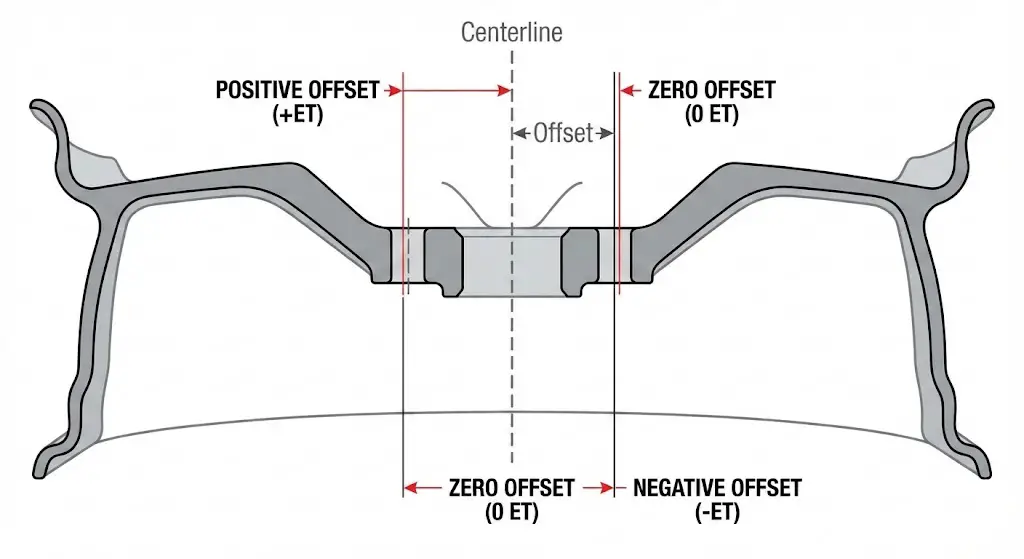
Wheel offset, denoted as "ET" (from the German Einpresstiefe, meaning "insertion depth"), is the measurement in millimeters from the hub mounting surface to the geometric centerline of the wheel. This single dimension is the most critical factor in suspension geometry preservation.
Positive Offset: The Factory Standard
Factory Super Duty wheels utilize a high positive offset, typically ranging from +40mm to +55mm depending on the generation and wheel width. In a positive offset configuration, the mounting surface is pushed toward the street-side face of the wheel, which effectively pulls the tire assembly inward, closer to the frame and suspension components.
- Engineering Purpose: High positive offset is designed to align the tire's centerline directly with the wheel bearings. This minimizes the lever arm acting on the unit bearing assembly, reducing the static and dynamic loads generated by the heavy diesel engine and payload.
- Scrub Radius Implication: This geometry creates a near-zero or slightly positive scrub radius—the distance between the point where the steering axis inclination (SAI) intersects the ground and the center of the tire contact patch. This ensures neutral steering feel and stability under heavy braking.
Negative Offset: The Aftermarket Aggressor
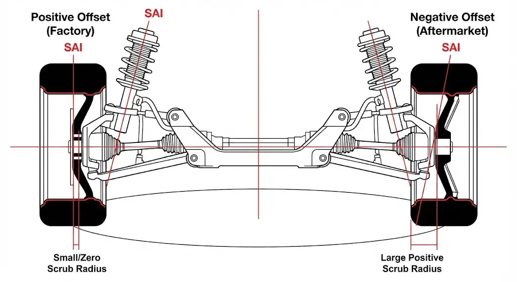
Conversely, the aftermarket community frequently favors negative offset wheels (e.g., -12mm, -24mm, -44mm). In this configuration, the mounting surface is closer to the brake side, pushing the wheel outward to create a "deep dish" appearance and a wider track width.
- Mechanical Consequence: While aesthetically aggressive, negative offset fundamentally alters the suspension physics. A -44mm offset wheel on a Super Duty moves the tire centerline outward by over 3 inches compared to stock. This creates a massive positive scrub radius.
- The Leverage Effect: As the scrub radius increases, the tire no longer pivots on a point during steering inputs; it scrubs in a wide arc. This dramatically increases the force required to turn the wheels, placing immense strain on the power steering pump, steering box sector shaft, and drag link. It acts as a "longer pry bar" on the ball joints, accelerating wear and fatigue.
Backspacing vs. Offset
While offset is a fixed metric relative to the centerline, backspacing is a measurement of physical clearance, defined as the distance from the mounting surface to the back lip of the wheel (measured in inches).
- Interrelation: Backspacing is a function of both offset and wheel width. For example, a 9-inch wide wheel with 0mm offset has a backspacing of roughly 5.0 inches.
- Clearance Criticality: On the Super Duty platform, backspacing is the primary determinant of whether a tire will rub suspension components. The transition from leaf springs to radius arms in 2005 necessitated a change in backspacing requirements to allow the wheels to turn sharply without contacting the radius arms.
Bolt Pattern (PCD) Architecture
The Pitch Circle Diameter (PCD) represents the diameter of the circle that passes through the center of the wheel lugs. The Super Duty ecosystem is unique in its fragmentation of bolt patterns based on capability and chassis type.
- 8x170mm: The ubiquitous standard for Single Rear Wheel (SRW) F-250 and F-350 trucks. This metric pattern was introduced in 1999 to replace the imperial 8x6.5" pattern used on previous OBS (Old Body Style) Fords, preventing the interchanging of wheels with insufficient load ratings.
- 8x200mm: A heavier-duty pattern introduced for the F-350 Dual Rear Wheel (DRW) and specific generations of the F-450 pickup to accommodate larger hub structures and higher clamping loads.
- 10x225mm: The commercial standard. Used on F-450/F-550 Chassis Cabs and select F-450 pickups, this pattern utilizes ten lugs to secure the massive 19.5-inch commercial wheels required for gross vehicle weights exceeding 14,000 lbs.
The Hub Bore and Center-Centricity
The Ford Super Duty utilizes a hub-centric wheel design. This means the weight of the vehicle is supported by the fitment of the wheel's center bore over the axle hub lip, not by the shear strength of the wheel studs. The studs merely provide the clamping force to keep the wheel flush.
- Specification: The standard hub bore for F-250/F-350 SRW models is 124.9mm.
- Fitment Risk: Attempting to mount a wheel with a smaller bore (e.g., from a different manufacturer) is impossible. Conversely, mounting a wheel with a larger bore (lug-centric) without hub-centric rings transfers all vertical impact loads to the studs, leading to vibration and potential stud failure.
The Single Rear Wheel (SRW) Evolution: F-250 & F-350
The Single Rear Wheel configuration represents the highest volume of Super Duty production. While the 8x170mm bolt pattern has remained a constant for over two decades, the offset and backspacing requirements have shifted dramatically in response to chassis updates.
First Generation (1999–2004): The Leaf Spring Era
The launch of the Super Duty in early 1998 (as a 1999 model) marked the separation from the F-150. The 4WD models of this generation utilized a solid front axle suspended by leaf springs.
- Suspension Architecture: Leaf springs are physically bulky and mounted outboard of the frame rails. This limited the space available for tires to turn inward.
- Wheel Specifications:
- Bolt Pattern: 8 x 170mm.
- Stock Wheel Size: 16x7 or 16x8 inches.
- Stock Offset: Lower positive offset, typically +6mm to +20mm.
- Lug Studs: M14 x 2.0 (Coarse Thread).
- Fitment Dynamics: Because the leaf springs restricted turning angle, the axles were narrower. Consequently, wheels needed less positive offset (sitting further out) to prevent the tires from rubbing the springs. Modern high-positive offset wheels (+40mm) from newer trucks will rub the leaf springs instantly on these models.
First Generation Refresh (2005–2007): The Coil Spring Revolution
The 2005 model year brought the most significant suspension change in the platform's history. Ford abandoned front leaf springs on 4WD models in favor of a coil spring suspension located by radius arms.
- Engineering Shift: To improve the turning radius—a major complaint of the leaf-sprung trucks—Ford widened the front axle track width significantly. This allowed the tires to turn sharper angles.
- Wheel Adaptation: To keep the tires tucked under the fenders despite the wider axle, Ford drastically increased the wheel offset.
- Wheel Specifications:
- Bolt Pattern: 8 x 170mm.
- Stock Wheel Size: Increased to 17-inch, 18-inch, and 20-inch options to clear larger brakes.
- Stock Offset: Jumped to +40mm to +45mm.
- Lug Studs: Changed to M14 x 1.5 (Fine Thread).
- Retrofit Warning: This bifurcation creates a compatibility trap. You cannot safely mount 2005+ wheels on a 1999–2004 truck without massive spacers (to clear the springs). Conversely, mounting 1999–2004 wheels on a 2005+ truck will cause them to stick out nearly 2 inches past the fender, wreaking havoc on the scrub radius and wheel bearings.
The "Alumiduty" Era (2017–2022)
The introduction of the aluminum-body Super Duty (P558) brought a stiffer fully-boxed frame and further suspension refinements.
- Clearance Challenges: Despite the massive physical size of the truck, the radius arms on the 2017–2022 models are positioned in a way that creates a clearance bottleneck for 35-inch and 37-inch tires.
- Stock Wheel Limits: The factory +40mm offset tucks the tires in so deeply that a 35x12.50 tire will rub the radius arms at full steering lock. This "radius arm rub" is a defining characteristic of this generation's fitment struggles.
- Optimal Aftermarket Offset: To clear 37s on a leveled suspension, a wheel offset of +18mm to +20mm is generally considered the "Goldilocks" zone—pushing the tire out just enough to clear the radius arm without forcing it into the fender or bumper crash bars.
The High-Output Modern Era (2023–2026)
With the P708 generation, Ford engineers directly addressed the radius arm complaints of the previous generation.
- Frame & Suspension Revision: The 2023+ trucks feature radius arms with a specific "notch" or clearance bend near the tire interface. Additionally, the wheel wells appear marginally larger or better shaped for clearance.
- Fitment Breakthrough: It is now possible to mount 37x12.50R20 tires on the stock +40mm wheels with little to no rubbing on the radius arms, a feat impossible on the 2017–2022 trucks without spacers.
- Hub Carryover: The bolt pattern (8x170mm) and hub bore (124.9mm) remain unchanged, preserving backward compatibility for wheels, provided the offset is appropriate.
SRW Technical Specifications Matrix (1999–2026)
| Model Years | Chassis Code | Bolt Pattern | Stud Thread | Center Bore | Stock Offset | Suspension Type (Front) |
| 1999–2004 | PHN131 | 8 x 170mm | M14 x 2.0 | 124.9mm | +6mm to +20mm | Leaf Spring (4WD) |
| 2005–2007 | PHN131 | 8 x 170mm | M14 x 1.5 | 124.9mm | +40mm to +45mm | Coil / Radius Arm |
| 2008–2010 | P356 | 8 x 170mm | M14 x 1.5 | 124.9mm | +40mm to +45mm | Coil / Radius Arm |
| 2011–2016 | P473 | 8 x 170mm | M14 x 1.5 | 124.9mm | +40mm to +45mm | Coil / Radius Arm |
| 2017–2022 | P558 | 8 x 170mm | M14 x 1.5 | 124.9mm | +40mm to +55mm | Coil / Radius Arm |
| 2023–2026 | P708 | 8 x 170mm | M14 x 1.5 | 124.9mm | +40mm to +60mm | Coil / Radius Arm (Notched) |
The F-450 & Dually Anomaly: A Guide to the 8x200 vs. 10x225 Confusion
Perhaps the most confusing aspect of the Super Duty ecosystem is the bolt pattern divergence found in the Dual Rear Wheel (DRW) F-350 and the F-450. Unlike the standardized F-250, the F-450 has oscillated between being a "beefed up F-350" and a "de-rated commercial truck," resulting in bolt pattern incompatibility that frequently traps owners.
The F-450 Identity Crisis
The F-450 exists in two distinct forms: the Pickup (with a factory-installed bed) and the Chassis Cab (incomplete vehicle for commercial upfitting).
Phase 1: The Commercial Standard (1999–2004)
In the beginning, the F-450 was strictly a chassis cab. It utilized a heavy-duty 8x225mm pattern, later evolving into the 10-lug standard. There was no consumer "pickup" version during these years.
Phase 2: The 10-Lug Pickup Debut (2008–2010)
In 2008, Ford introduced the F-450 Pickup. This truck was essentially a re-badged F-450 Chassis Cab with a pickup bed.
- Bolt Pattern: 10 x 225mm.
- Wheels: 19.5-inch commercial wheels.
- Axle: The massive "Wide Track" Dana Super 60 front axle, allowing for an incredibly tight turning circle despite the truck's size.
Phase 3: The "Neutered" Years (2011–2014/16)
This is the period of maximum confusion. For the 2011 redesign (introduction of the 6.7L Powerstroke), Ford sought to make the F-450 Pickup more fuel-efficient and comfortable. They effectively moved the F-450 pickup onto the F-350 DRW frame.
- The Change: The 2011–2014 F-450 Pickup LOST the wide-track front axle and the 19.5-inch 10-lug wheels.
- Bolt Pattern: It switched to the F-350 DRW standard of 8 x 200mm.
- Wheels: It used standard 17-inch dually wheels.
- Compatibility: A 2012 F-450 Pickup cannot mount wheels from a 2010 F-450 or a 2012 F-450 Chassis Cab (which retained the 10x225mm pattern). This is a critical distinction when sourcing replacement wheels.
Phase 4: The Return to Commercial Roots (2017–2026)
Responding to customer complaints about the loss of the tight turning radius, Ford reverted the F-450 Pickup back to the commercial chassis specs in 2017.
- Bolt Pattern: Returned to 10 x 225mm.
- Wheels: Returned to 19.5-inch commercial wheels.
- Differentiation: This makes visual identification easy on modern trucks. If it has 8 lugs, it is an F-350 DRW. If it has 10 lugs, it is an F-450 (or F-550).
F-450 & F-350 DRW Bolt Pattern Matrix
| Model Year | F-350 DRW | F-450 Pickup | F-450 Chassis Cab |
| 1999–2004 | 8 x 170mm (SRW Axle) | N/A (No Pickup) | 8 x 225mm |
| 2005–2007 | 8 x 200mm | N/A (No Pickup) | 10 x 225mm |
| 2008–2010 | 8 x 200mm | 10 x 225mm | 10 x 225mm |
| 2011–2014 | 8 x 200mm | 8 x 200mm | 10 x 225mm |
| 2015–2016 | 8 x 200mm | 8 x 200mm* | 10 x 225mm |
| 2017–2026 | 8 x 200mm | 10 x 225mm | 10 x 225mm |
Fitment & Clearance: The 35" and 37" Tire Guide
The primary driver for researching offset charts is the desire to fit larger tires. The Super Duty's large wheel wells invite 35-inch and 37-inch rubber, but the suspension components often disagree.
The Radius Arm Constraint
The radius arm suspension design provides excellent stability but occupies physical space directly behind the tire.
- The Conflict: When turning the steering wheel to full lock, the back inside edge of the tire swings inward. If the wheel offset is too high (e.g., stock +40mm), the tire is "sucked in" and contacts the radius arm.
- The Solution: Lowering the offset (moving the tire out) resolves this, but pushing it out too far causes the front of the tire to hit the bumper or the rear of the tire to hit the fender liner (pinch weld).
Gen 4 (2017–2022) Fitment Strategy
For this generation, the radius arms are the limiting factor.
- Leveling Kit (2.0" - 2.5"):
- 35x12.50R20: Fits on stock wheels (+40mm) but will rub the radius arms. A +18mm offset aftermarket wheel eliminates the rub and fits perfectly without trimming.
- 37x12.50R20: Requires a leveling kit. On stock wheels, rubbing is severe. The ideal offset is +18mm to +20mm. This allows clearance of the radius arm while tucking the tire just enough to avoid cutting the front bumper crash bars. Zero offset (0mm) or negative offset (-12mm) with 37s on a leveling kit will almost certainly require trimming the metal crash brackets.
Gen 5 (2023–2026) Fitment Strategy
The 2023+ trucks are far more accommodating.
- Stock Suspension:
- 35x12.50R20: Fits on stock wheels with no rubbing.
- Leveling Kit (2.0" - 2.5"):
- 37x12.50R20: Can be run on stock wheels (+40mm) with minimal to no radius arm rub due to the new notched arm design.
- Aftermarket Wheels: A +18mm or +20mm offset remains the ideal stance for a flush look, but the aggressive 0mm offset is more forgiving on this generation regarding fender clearance.
Comprehensive Tire Fitment Matrix (F-250/F-350 SRW)
| Generation | Suspension | Tire Size | Wheel Width | Ideal Offset | Modification Required |
| 2017–2022 | Stock | 295/65R20 (35.1") | 8.0" (Stock) | +40mm | None (Slight rub at lock) |
| 2017–2022 | 2.5" Level | 35x12.50R20 | 9.0" | +18mm | None |
| 2017–2022 | 2.5" Level | 37x12.50R20 | 9.0" | +18mm | Minor Plastic Trimming |
| 2017–2022 | 2.5" Level | 37x12.50R20 | 9.0" | 0mm | Metal Crash Bar Trimming |
| 2017–2022 | 4.0" Lift | 37x13.50R20 | 10.0" | -12mm | Minor Trimming |
| 2023–2026 | Stock | 35x12.50R20 | 8.0" (Stock) | +40mm | None |
| 2023–2026 | 2.5" Level | 37x12.50R20 | 8.0" (Stock) | +40mm | None (Verify Radius Arm clearance) |
| 2023–2026 | 2.5" Level | 37x12.50R20 | 9.0" | +18mm | None |
Mechanical Consequences: Death Wobble & Component Failure
It is impossible to discuss Super Duty wheel offset without addressing the mechanical repercussions of aggressive fitment. The solid axle design is robust but geometrically sensitive.
The "Death Wobble" Connection
"Death Wobble" is a violent, uncontrollable oscillation of the front axle, typically triggered by hitting a bump at highway speeds.
- Mechanism: It occurs when the lateral forces acting on the tires overcome the stabilizing forces of the track bar and steering damper.
- Offset's Role: Installing high negative offset wheels (e.g., -44mm) creates a massive lever arm. Every bump the tire hits exerts a magnified torque on the steering knuckle. This increased leverage accelerates wear on the track bar ball joint. Once the track bar bushing or ball joint develops play (even 1/16th of an inch), the axle is free to oscillate laterally, initiating Death Wobble.
- Mitigation: If running negative offset wheels, it is imperative to upgrade the track bar to a rigid, adjustable aftermarket unit and install dual steering stabilizers to dampen the increased feedback forces.
Wheel Bearing & Hub Stress
The unit bearings on the Super Duty are sealed assemblies.
- Load Center: They are engineered for the factory +40mm offset, which places the vehicle's weight directly in line with the ball bearings.
- Leverage: A -44mm offset wheel shifts the load center outward by over 3 inches. This creates a constant prying force on the top of the bearing.
- Maintenance: Owners with high negative offset wheels should expect significantly reduced bearing life. which highlights the premium price of these heavy-duty hub assemblies.
Power Steering Strain
The increased scrub radius caused by negative offset wheels requires significantly more force to turn the steering wheel, especially when the vehicle is stopped (static steering).
- Failure Point: This creates excessive heat and pressure in the power steering pump and hydro-boost system. It is not uncommon for the sector shaft seals in the steering gear to fail prematurely on trucks running 37x13.50 tires on -24mm wheels.
Commercial & Dually Considerations
For the F-350 DRW and F-450 owners, wheel upgrades are further complicated by the spacing between the dual rear wheels.
The "Kissing" Sidewall Danger
When installing wider tires (e.g., 12.50 wide) on a dually, the gap between the rear tires narrows.
- Risk: Under load, the sidewalls of the tires bulge. If the rear tires touch ("kiss"), the friction generates immense heat, leading to catastrophic blowout of both rear tires.
- Solution: When moving to 12.50 wide tires on a dually, a hub-centric wheel spacer (typically 2 inches) is required between the duals to maintain a safe air gap.
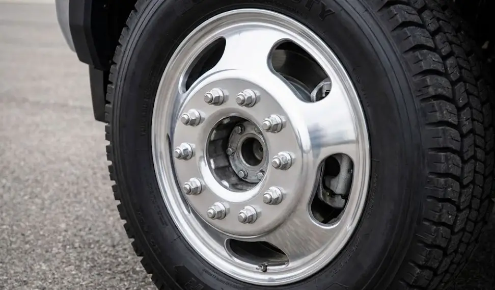
The 19.5" Commercial Wheel Dilemma
Owners of F-450s often dislike the harsh ride of the 19.5-inch commercial tires (Load Range G/H).
- Conversion: Many seek to convert to "Super Singles" (removing the duals for a single large off-road tire).
- Engineering Challenge: The 10x225mm bolt pattern is rare in the consumer aftermarket. Specialized wheels, such as military-grade Hutchinson beadlocks or custom forged wheels, are required.
- Safety Note: Never use adapters to convert a 10-lug truck to an 8-lug wheel. The Gross Axle Weight Rating (GAWR) of an F-450 rear axle often exceeds 9,000 lbs. Standard 8-lug wheels are not rated for these loads, creating a severe safety hazard.10 For a deeper understanding of towing loads, consult the(https://fordmasterx.com/comprehensive-engineering-analysis-and-operational-guide-the-2023-ford-f-250-towing-capacity-architecture/).
Aftermarket Wheel Ecosystem & Maintenance
Maintenance Protocols
Modifying wheel geometry demands stricter maintenance schedules.
- Torque Sequence: Always follow a star pattern.
- Re-Torque: Alloy wheels must be re-torqued after the first 50-100 miles.
- Specs:
- 1999-2002 (M14x2.0): 150-165 ft-lbs.
- 2003-2026 (M14x1.5): 165 ft-lbs.
- Emergency Access: Maintenance often requires under-hood access. If mechanical failures occur, review the Critical Emergency Guide: How to Open a Ford F-250 Hood from the Outside.
Frequently Asked Questions (FAQ)
What is the maximum tire size for a stock 2024 F-250?
Thanks to the 2023 redesign, you can fit 35x12.50R20 tires on stock wheels with no rubbing. Some owners have successfully fitted 37x11.50 tires on stock suspension, though this fills the wheel well completely.
Why won't my old 8x170 wheels fit my new 2024 Super Duty?
While the bolt pattern (8x170mm) is the same, the backspacing requirements may differ if the wheels are from a pre-2005 truck. Additionally, check the wheel diameter. Modern Super Duties with larger brakes (especially F-350s with the Max Tow package) generally require a minimum of 18-inch or 20-inch wheels to clear the calipers; 16-inch and some 17-inch wheels will not fit.
How do I tell if my F-450 has the 8-lug or 10-lug pattern?
Count the lugs. If it is a 2011–2016 F-450 Pickup, it likely has 8 lugs (8x200mm). If it is a 2008–2010 or 2017+ F-450, it will have 10 lugs (10x225mm). Chassis Cabs almost always use the 10-lug pattern regardless of year.
Does offset affect towing capacity?
Indirectly, yes. While the engine's power remains the same, moving the wheels outward (negative offset) increases the leverage on the axle housing. This can technically derate the effective payload capacity due to increased stress on the wheel bearings and axle tubes. Stick to high-positive offset wheels for maximum towing safety.
What is the hub bore size for the Ford Super Duty?
For all F-250 and F-350 SRW models from 1999 to present, the hub bore is 124.9mm. Ensure any aftermarket wheels are "Hub Centric" to this specification to avoid vibration issues.