Ford Ranger Fuse Box Diagram: Easy Setup Guide
The 1995 Ford Ranger fuse box diagram maps the interior panel behind the driver’s side kick panel and the engine bay power distribution box. This guide identifies fuses for the ECU and fuel pump, helping you resolve electrical failures or a check engine light by locating the correct circuit for repair.
📌 Key Takeaways
- The diagram serves as a map to identify which fuse controls specific electrical components.
- The Power Distribution Box in the engine bay is critical for high-draw items like the starter and ECU.
- Always replace a blown fuse with one of the exact same amperage to prevent electrical fires.
- Use a multimeter to test for continuity if a fuse visual inspection is inconclusive.
- Use this diagram whenever an electrical component fails or a diagnostic code points to a circuit issue.
Navigating the electrical system of a classic pickup requires precision, and having a reliable 1995 Ford Ranger fuse box diagram is the essential first step for any DIY mechanic or enthusiast. Whether you are dealing with a sudden loss of interior lighting, a radio that refuses to power on, or a more critical issue like a non-starting engine, the fuse box is your first line of defense and diagnosis. This comprehensive guide will walk you through the identification of every circuit, the physical location of the panels, and the practical steps needed to troubleshoot electrical faults. By understanding the layout of your Ranger’s electrical protection system, you will be equipped to handle repairs that keep your truck on the road and functioning at its peak performance.

Comprehensive Layout of the 1995 Ford Ranger Fuse Panels
The 1995 Ford Ranger utilizes a bifurcated electrical protection system, meaning it splits its fuses and relays between two distinct locations. This design ensures that high-current engine components are separated from sensitive cabin electronics. Understanding both locations is vital because a failure in one can often mimic a failure in the other.
1. The Passenger Compartment Fuse Panel
This panel is located inside the cabin, specifically on the driver’s side dashboard. To access it, you must open the driver-side door and look for a removable plastic panel on the side of the dash. This interior panel typically houses smaller “Mini” fuses ranging from 5 to 30 amps. These protect the 1995 Ford Ranger’s interior accessories, instrument cluster, and lighting circuits. Because this area is susceptible to vibration and temperature changes from the cabin heater, ensuring the fuses are seated firmly is a common maintenance task.
2. The Power Distribution Box (Engine Bay)
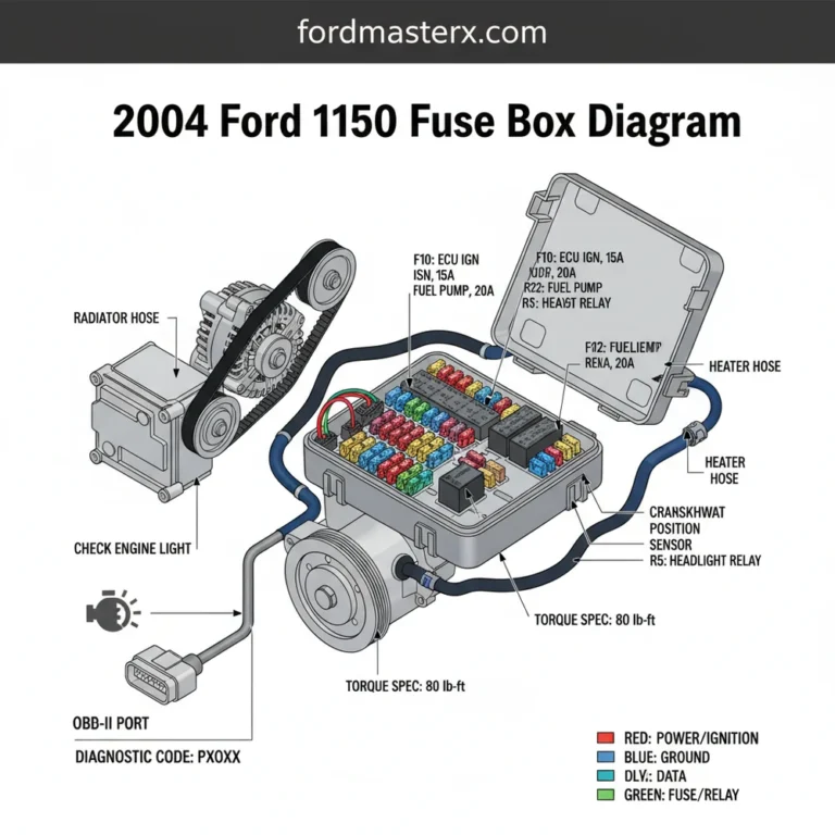
The second, and arguably more critical, component is the Power Distribution Box located under the hood. You will find this black plastic box on the driver’s side fender well, usually situated behind the battery and near the brake master cylinder. This box contains “Maxi” fuses and high-current relays. It controls heavy-duty components such as the ECU (Engine Control Unit), fuel pump, starter solenoid, and the ABS system. The diagram for this box is often embossed on the underside of its plastic lid, though it can become illegible over decades of engine heat.
In the 1995 model year, Ford transitioned heavily toward the OBD-II standard. This means the fuse responsible for the cigarette lighter (Fuse #17 in the interior panel) is also responsible for providing power to the OBD-II diagnostic port. If your code reader won’t turn on, check this fuse first!
[DIAGRAM_PLACEHOLDER – 1995 Ford Ranger Fuse Box Layout Map: Interior Panel (Left) and Engine Bay Power Distribution Box (Right) with color-coded amperage indicators]
Step-by-Step Guide: How to Read and Interpret the Diagram

Reading a 1995 Ford Ranger fuse box diagram involves more than just matching numbers; it requires an understanding of how electricity flows through your truck’s harness. Follow these steps to correctly identify and replace a faulty circuit.
Step 1: Gather the Necessary Tools
Before touching the fuse box, gather a few basic tools. You will need a pair of plastic fuse pullers (usually found inside the fuse box cover), a digital multimeter or a 12V test light, and a flashlight. If you are working on the engine bay box, a socket set might be necessary if you need to clean the battery terminals to ensure proper current flow.
Step 2: Locate the Blown Fuse
Using your 1995 Ford Ranger fuse box diagram, identify the fuse associated with your malfunctioning component. For example, if your wipers are dead, look for the wiper motor circuit. Once identified, look at the fuse through its transparent plastic housing. If the metal link inside is broken or the plastic is charred, the fuse has “popped” to protect the circuit.
Step 3: Test for Power with a Test Light
With the ignition in the “On” or “Accessory” position, touch the probe of your test light to the small metal contact points on the back of the fuse. If the test light glows on one side but not the other, the fuse is definitely blown. If it glows on both sides, the fuse is good, and the problem likely lies deeper in the wiring or the component itself.
Step 4: Verify Amperage Ratings
Never replace a fuse with one of a higher amperage rating. If the diagram calls for a 15A (Blue) fuse, do not use a 20A (Yellow) fuse. Doing so risks melting the wiring harness or causing an electrical fire. The 1995 Ranger uses a standardized color-coding system:
- ✓ 10 Amp: Red
- ✓ 15 Amp: Blue
- ✓ 20 Amp: Yellow
- ✓ 30 Amp: Green
Step 5: Inspect the Relay (Engine Bay Only)
If the fuse is intact but the component (like the fuel pump) isn’t working, you must test the relay. Relays are essentially remote-controlled switches. In the 1995 Ranger, the ECU relay is a frequent point of failure. You can often swap a known-good relay (like the horn relay) with the suspect relay to see if functionality returns.
Always turn off the engine and disconnect the negative battery terminal before working on high-amperage fuses in the Power Distribution Box to prevent accidental shorts or shocks.
Common Issues and Troubleshooting with the Fuse Box

The 1995 Ford Ranger is known for a few specific electrical quirks. One of the most common issues involves the check engine light. If your truck is running poorly and the light is illuminated, you would normally use a scanner to pull a diagnostic code. However, if the fuse for the ECU or the data link connector is blown, your scanner will fail to communicate. This often leads owners to believe their computer is dead when, in reality, it’s just a $1 fuse.
Another frequent problem involves the coolant flow sensor or the electric cooling fans (on specific engine configurations). If these fuses blow, the engine can overheat rapidly. Always cross-reference your fuse diagram if you notice the temperature gauge climbing. Furthermore, internal shorts in the steering column can cause the turn signal fuse to blow repeatedly. In these cases, the diagram helps you isolate the circuit so you can trace the wire for a pinch point or “ground out” condition.
If you experience intermittent electrical power loss, check the battery terminal connections. The torque spec for these terminals is usually around 10-13 lb-ft. Loose terminals can cause “arcing” which may blow sensitive fuses in the Power Distribution Box.
Maintenance and Best Practices for Long-Term Reliability
To keep your Ranger’s electrical system healthy, a proactive approach is required. Electrical components do not exist in a vacuum; they are influenced by the mechanical state of the truck. For example, a worn accessory belt can cause the alternator to slip, leading to low voltage output. This low voltage forces components to pull more amperage, which can prematurely weaken or blow fuses.
Similarly, while the timing chain is a mechanical component, the sensors that monitor it (like the Crankshaft Position Sensor) rely on clean power from the Power Distribution Box. Keeping the fuse box clean and free of moisture is vital. Over time, engine bay heat can make the plastic fuse box brittle. Applying a small amount of dielectric grease to the fuse blades can prevent corrosion and ensure a solid connection in high-humidity environments.
When purchasing replacement parts, avoid the “no-name” bulk fuse packs found at discount stores. These often lack the precise “fast-blow” characteristics required to protect sensitive electronics like the ECU. Stick with reputable brands like Bussmann or Littelfuse to ensure your 1995 Ford Ranger stays protected.
By keeping a printed copy of the 1995 Ford Ranger fuse box diagram in your glove box, you are prepared for roadside emergencies. This simple document is the map to your truck’s nervous system, allowing you to bypass expensive shop diagnostic fees and handle the repair yourself with confidence.
In summary, the 1995 Ford Ranger fuse box diagram is an indispensable tool for maintaining your vehicle. From managing the critical power flow to the ECU to ensuring your diagnostic port is ready for an OBD-II scanner, the fuse box is central to your truck’s operation. Regular inspection, proper tool usage, and adherence to amperage ratings will ensure your Ranger remains a reliable workhorse for years to come.
Frequently Asked Questions
Where is the fuse box located?
The 1995 Ford Ranger has two fuse locations. The interior fuse panel is behind a plastic cover on the driver’s side kick panel, near the brake pedal. The high-power distribution box is located in the engine compartment on the driver’s side fender well, near the battery.
What does the fuse box diagram show?
The diagram illustrates the physical layout of fuses and relays, assigning a specific number to each. It details the amperage rating for every slot and identifies which vehicle system each fuse protects, such as the fuel pump, radio, headlights, or the OBD-II diagnostic port power circuit.
How many connections does the fuse box have?
The interior panel typically features 18 to 24 fuse slots, while the engine bay power distribution box contains several high-current maxi-fuses and relays. Each fuse slot has two primary metal terminals that complete the circuit when a functional fuse is inserted, ensuring power reaches the intended component.
What are the symptoms of a bad fuse?
Common symptoms include a specific electrical component suddenly stopping, such as the radio or wipers, or a check engine light triggered by a lack of power to the ECU. If your OBD-II scanner won’t power up, it often indicates a blown fuse in the cigarette lighter circuit.
Can I replace the fuses myself?
Yes, replacing a fuse is a simple DIY task. Once you locate the correct fuse using the diagram, you simply pull the old one out and push a new one in. It requires no specialized mechanical knowledge and can save you a costly trip to a professional mechanic.
What tools do I need for this task?
You primarily need a plastic fuse puller tool, which is often stored inside the fuse box cover. A digital multimeter is helpful for testing continuity without removing the fuse. If you are tightening the power distribution box terminals, ensure you follow the 5-8 lb-in torque spec.