Ford Mondeo 2.0 TDCI Engine Diagram: Layout Guide
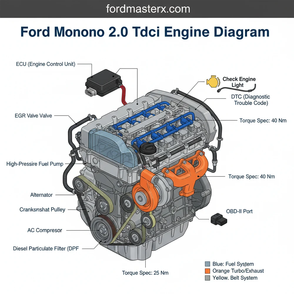
A Ford Mondeo 2.0 TDCI engine diagram provides a visual layout of the fuel system, turbocharger, EGR valve, and cooling components. It serves as a roadmap for locating the ECU, sensors, and mechanical assemblies, allowing for precise part identification and efficient troubleshooting of the common Duratorq diesel engine platform.
📌 Key Takeaways
- Visualizes the layout of the Duratorq fuel and air systems
- EGR valve and Turbocharger are the most critical components to identify
- Ensure all electrical connectors are clean before reassembly
- Reference the diagram when verifying vacuum hose routing
- Ideal for diagnosing power loss or starting issues
Understanding the intricate layout of a ford mondeo 2.0 tdci engine diagram is the cornerstone of successful vehicle maintenance and repair. Whether you are performing a routine service or investigating a complex performance issue, having a reliable visual reference allows you to locate critical sensors, fluid paths, and mechanical linkages with confidence. This guide provides a detailed breakdown of the 2.0 TDCi architecture, covering everything from the timing chain configuration to electrical connections. You will learn how to interpret technical drawings to streamline your workflow and avoid costly mistakes during engine repairs.
The ford mondeo 2.0 tdci engine diagram typically illustrates the Duratorq DW10 engine family, a powerhouse known for its balance of efficiency and torque. When viewing the diagram, the most prominent features are the high-pressure fuel system components and the induction path. At the top of the engine, you will identify the common rail fuel delivery system, which includes the high-pressure pump, the fuel rail itself, and the electronically controlled injectors. These components are critical for maintaining the precise fuel atomization required for modern diesel emissions standards.
The diagram also highlights the cooling system and air intake architecture. The coolant flow path is visualized through a series of hoses connecting the radiator, thermostat housing, and the internal water jacket within the block. On the air induction side, the diagram maps the route from the air filter box through the turbocharger, intercooler, and finally into the intake manifold. This visual mapping is essential for identifying vacuum leaks or boost pressure losses that can sap engine power.
To the side of the engine block, the diagram outlines the accessory belt drive system, often referred to as the serpentine belt. This belt powers the alternator, air conditioning compressor, and power steering pump. Internally, though often represented by a separate overlay, the timing chain or belt mechanism (depending on the specific generation of the 2.0 TDCi) is documented to show the synchronization between the crankshaft and the dual overhead camshafts. This synchronization is the heartbeat of the engine, ensuring that valves open and close at precisely the right millisecond relative to piston position.
The 2.0 TDCi engine utilizes a sophisticated Electronic Control Unit (ECU) to manage variables such as fuel pressure, turbo vane geometry, and Exhaust Gas Recirculation (EGR). Always cross-reference your specific engine code (found on the door pillar or engine block) with the diagram to ensure component compatibility.
Reading a ford mondeo 2.0 tdci engine diagram requires a systematic approach to translate the two-dimensional drawing into three-dimensional mechanical action. Follow these steps to master the interpretation of your engine’s layout:
1. Orient the Perspective: Most diagrams are drawn from the perspective of standing at the front bumper looking toward the cabin. Identify the “front” of the engine, which is the side with the accessory belt, and the “rear,” which connects to the transmission. This orientation prevents you from confusing the left (passenger side) and right (driver side) components.
2. Identify the Major Systems: Before diving into small bolts, locate the primary systems. Use the diagram to find the cooling system (indicated by flow arrows), the fuel system (indicated by high-pressure lines), and the electrical harness. The ECU is usually depicted as the central hub where all sensor lines converge.
3. Trace the Air and Coolant Flow: Understanding the coolant flow is vital for overheating diagnostics. Start at the water pump on the diagram and follow the path through the engine block, out through the thermostat, and into the radiator. Similarly, trace the air intake path from the turbocharger to the intake manifold to identify where sensors like the MAP (Manifold Absolute Pressure) sensor are located.
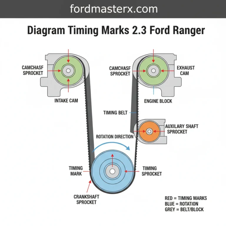
4. Locate the Timing Markers: If you are performing a timing chain or belt service, the diagram will highlight “TDC” (Top Dead Center) marks. These are physical notches on the crankshaft pulley and camshaft gears that must align perfectly. Never rotate the engine without verifying these marks against the diagram.
5. Identify Electronic Sensors: The diagram will label various sensors that communicate with the ECU. Locate the Crankshaft Position Sensor (CKP), Camshaft Position Sensor (CMP), and the Mass Air Flow (MAF) sensor. Knowing their exact location allows you to perform “pin-out” tests with a multimeter if you suspect a wiring fault.
6. Check the Accessory Belt Routing: One of the most common uses for an engine diagram is re-installing the accessory belt. The diagram shows the specific “snake” pattern the belt must take around the tensioner, idler pulleys, and various pumps. An incorrect routing can lead to immediate belt failure or reversed pump rotation.
7. Verify Torque Specifications: While the diagram shows where parts go, the accompanying data sheet usually provides the torque spec for each bolt. This is especially important for the fuel injectors and cylinder head bolts, where over-tightening can cause catastrophic engine damage.
Before working on any electrical or fuel components shown in the diagram, disconnect the battery. The 2.0 TDCi fuel system operates at extremely high pressures (up to 2,000 bar); loosening a fuel line while the engine is running or recently turned off can cause severe injury.
Troubleshooting the Ford Mondeo 2.0 TDCi becomes much simpler when you use the diagram to isolate symptoms. One of the most frequent issues is the appearance of the check engine light on the dashboard. When this occurs, the ECU has detected a value outside of the normal operating range and stored a diagnostic code. By using an OBD-II scanner, you can retrieve this code (e.g., P0401 for EGR flow issues). You can then use the engine diagram to locate the specific component mentioned in the code, such as the EGR valve or the associated vacuum solenoids.
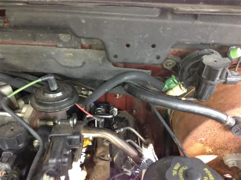
Another common problem involves “Limp Mode,” where the engine limits power to protect itself. This is often caused by a boost leak. By referencing the diagram’s air induction section, you can methodically check every hose and coupling between the turbo and the intake. If you notice oily residue on a hose highlighted in the diagram, you have likely found your leak. Similarly, if you experience hard starting, use the diagram to locate the glow plugs and the fuel filter to check for air ingress or electrical resistance issues.
- ✓ Check Engine Light: Use the diagram to find sensors related to specific P-codes.
- ✓ Coolant Leaks: Follow the coolant flow path to find hidden bypass hoses.
- ✓ Poor Performance: Inspect the vacuum lines shown in the diagram for cracks or collapses.
- ✓ Noisy Accessory Belt: Use the diagram to identify which pulley (alternator, AC, or idler) is misaligned.
To keep your 2.0 TDCi running efficiently, maintenance should be proactive rather than reactive. Always use a high-quality OBD-II diagnostic tool to clear old codes and monitor live data. When replacing components, ensure you adhere to every torque spec mentioned in your service manual; the aluminum components in the Mondeo engine are sensitive to over-torquing, which can strip threads easily.
When replacing the accessory belt, always check the condition of the tensioner pulley. If the pulley shows any lateral play or makes a “gritty” sound when spun by hand, replace it immediately to prevent the new belt from snapping.
Maintenance of the timing chain or belt is another critical area. While many modern 2.0 TDCi engines use a “long-life” chain, the guides and tensioners can wear over time. If you hear a rattling sound from the side of the engine shown in your ford mondeo 2.0 tdci engine diagram, it is time for an inspection. Furthermore, ensure you are using the correct oil grade (typically 5W-30 meeting Ford WSS-M2C913-C or D specifications). Diesel engines are highly sensitive to oil quality because the oil also lubricates the turbocharger bearings, which spin at tens of thousands of RPMs.
Finally, keep the engine bay clean. A clean engine makes it much easier to compare the physical hardware to your ford mondeo 2.0 tdci engine diagram. It allows you to spot fresh fluid leaks or frayed wires before they lead to a breakdown on the road. By combining a high-quality diagram with regular inspections and the right diagnostic tools, you can ensure your Ford Mondeo remains a reliable and powerful vehicle for years to come.
Step-by-Step Guide to Understanding the Ford Mondeo 2.0 Tdci Engine Diagram: Layout Guide
Identify the main engine cover and remove it to reveal the upper components.
Locate the fuel rail and injectors at the top center of the engine block.
Understand how the intake manifold connects to the turbocharger and EGR system.
Apply the diagram to trace vacuum lines for any leaks or cracks.
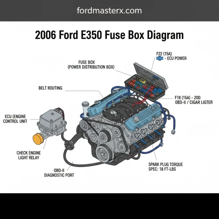
Verify that the OBD-II port is clear for scanning if a check engine light appears.
Complete the inspection by checking for any loose electrical connectors or sensors.
Frequently Asked Questions
Where is the ECU located on the Ford Mondeo?
The ECU is typically located behind the front wheel arch liner on the passenger side or under the plastic cowl near the firewall. Locating it via the engine diagram is crucial when tracing wiring faults or checking for water ingress that might trigger a diagnostic code.
What does this engine diagram show?
The diagram illustrates the physical arrangement of the 2.0 TDCI engine, including the fuel rail, injectors, high-pressure pump, and belt routing. It helps owners understand how air and fuel flow through the system and identifies the location of sensors that communicate with the OBD-II system.
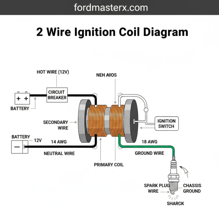
How many connections does a 2.0 TDCI fuel injector have?
Each fuel injector typically has a two-pin electrical connection and one high-pressure fuel line fitting. The engine diagram shows how these injectors are wired back to the main harness, which is essential for diagnosing cylinder misfires or electrical continuity issues within the fuel delivery system.
What are the symptoms of a bad EGR valve?
A failing EGR valve often triggers a check engine light and causes rough idling, reduced fuel economy, or limp mode. Using the diagram to locate the valve allows you to inspect it for carbon buildup, which is a frequent cause of performance-related diagnostic codes in diesel engines.
Can I replace the air filter myself?
Yes, replacing the air filter is a simple DIY task. The engine diagram identifies the airbox location, usually at the front of the engine bay. It requires basic tools to open the housing, making it an accessible maintenance project for most Ford Mondeo owners.
What tools do I need for engine maintenance?
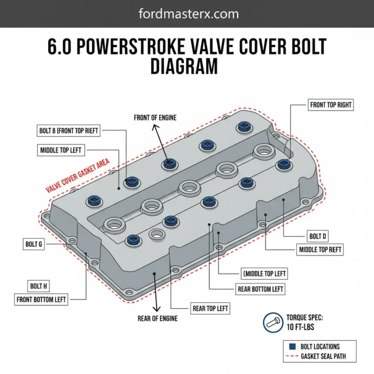
You will need a standard socket set, torx bits, and a reliable torque spec manual. For electronic diagnosis, an OBD-II scanner is vital to read codes. A torque wrench ensures that bolts for components like the valve cover are tightened to the manufacturer’s precise requirements.