Ford Heater Core Hose Diagram & Routing Guide: Inlet/Outlet ID, Diagnostics, and Repair Guides 2026
In the realm of modern automotive engineering, the heater core circuit is no longer a simple auxiliary loop for passenger comfort; it is an integral component of the engine’s total thermal management strategy. For Ford Motor Company, the evolution from the pushrod V8s of the 20th century to the complex, turbocharged, and variable-cam-timing engines of the present has necessitated a radical reimagining of coolant flow dynamics. The heater core now serves critical roles in engine warm-up acceleration, cylinder head temperature homogenization, and continuous air purging.
This report serves as an exhaustive technical manual for automotive technicians, enthusiasts, and engine builders. It synthesizes scattered technical data into a coherent operational theory, providing precise identification of inlet and outlet hoses, flow directionality, and diagnostic protocols for Ford’s most prevalent powertrains. We will explore the physics of heat transfer, the specific architectures of the Coyote, Triton, and EcoBoost families, and the distinct maintenance challenges posed by proprietary quick-connect fittings.
Visualizing the Loop: The Core Concept
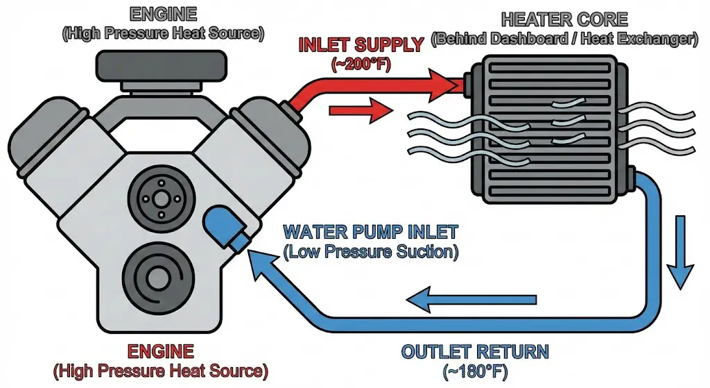
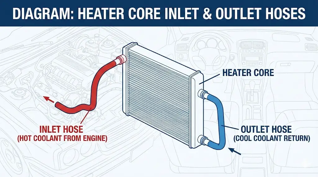
At a fundamental level, the heater core operates as a liquid-to-air heat exchanger. Its performance relies entirely on the pressure differential between the supply (inlet) and return (outlet) sides of the system.
- The Inlet (Supply): This line originates from a high-pressure zone within the engine—typically the cylinder head crossover, the intake manifold, or a dedicated supply tube leaving the water pump’s pressure side. It carries coolant at operating temperature (190°F–215°F).
- The Heat Exchanger (Core): Located inside the HVAC plenum behind the dashboard, the core consists of finned aluminum tubes. As the blower motor forces air across these fins, thermal energy is transferred from the coolant to the cabin air via convection.
- The Outlet (Return): This line returns the cooler fluid (typically 10°F–25°F cooler) to a low-pressure zone—such as the water pump inlet or a “Y” block connecting to the lower radiator hose.
While this loop seems elementary, Ford’s implementation varies wildly. Misidentifying these hoses can lead to inefficient heating, trapped air pockets (vapor locks), and in the case of engine swaps, catastrophic cylinder head overheating due to lack of purge flow.
Heater Core Diagnostics
Inlet/Outlet Routing & Thermal Flow Analysis
Understanding the Loop
The heater core relies on a continuous loop of high-pressure coolant. Diagnosing “no heat” requires understanding the flow direction. Typically, coolant flows from the engine intake/head (Inlet), through the firewall, into the core, and returns to the water pump (Outlet).
System Flow Diagram
Standard Ford Coolant Direction
Analysis: The Inlet hose carries the hottest coolant directly from the engine. The core acts as a radiator, dissipating heat into the cabin, resulting in a cooler Outlet hose.
Inlet vs. Outlet Temperature
Identifying Clogs via Thermal Delta
Key Insight: In a clogged system, the Inlet remains hot (pressure from engine), but flow stops, causing the Outlet to drop to near-ambient temperature. A delta >30°F usually indicates restriction.
Why Do Heater Cores Fail?
Common Causes in Vehicles >100k Miles
Key Insight: Internal clogging (sediment/sludge) is the primary killer. “Electrolysis” occurs when old coolant becomes acidic, eating the aluminum core from the inside out.
Hose Material Degradation Probability
Risk of Burst/Leak over Vehicle Age
Key Insight: Modern EPDM rubber hoses last longer, but plastic “Quick Connects” (common on Fords) become brittle and prone to cracking after year 10. Silicone hoses offer flatline reliability but higher cost.
© 2026 FordMasterX Data Visualization. All rights reserved.
Universal Identification and Diagnostic Physics
Before dissecting specific engine diagrams, it is vital to establish a universal methodology for identifying heater hoses on any Ford vehicle. Since diagrams are often unavailable or obfuscated by engine covers, the “First Principles” of thermodynamics provide the most reliable identification tools.
Thermal Differential Analysis (Delta T)
The definitive method for identifying flow direction is measuring temperature drop.
- Operational Theory: The engine is the heat source; the heater core is the heat sink. Therefore, the fluid entering the core must be hotter than the fluid exiting it.
- Diagnostic Procedure:
- Bring the engine to operating temperature (thermostat open).
- Turn the cabin heater to MAX HEAT and the blower to HIGH. This maximizes heat extraction.
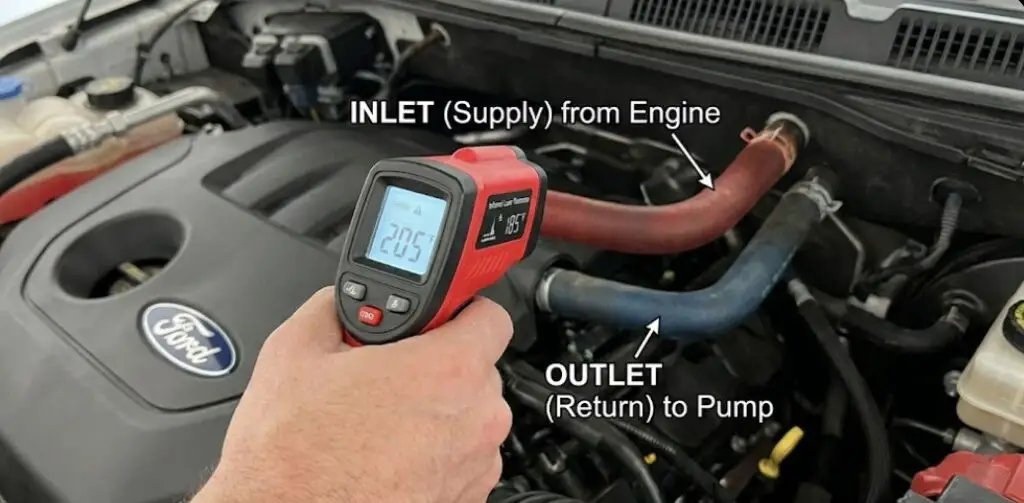
- Using an infrared non-contact thermometer or a thermal imaging camera, measure the surface temperature of both heater hoses at the firewall.
- Interpreting Data:
- Inlet: The hotter hose. It should closely match the engine coolant temperature (ECT).
- Outlet: The cooler hose. In a healthy system, this should be 10°F to 25°F cooler than the inlet.
- Fault Detection:
- Cold Outlet: A temperature drop of >50°F suggests a blockage. The coolant is moving so slowly that it sheds all its heat before exiting, or it isn’t moving at all.
- Cold Inlet & Outlet: This indicates an air lock, a failed water pump, or a closed heater control valve preventing flow entirely.
Physical Engineering Markers
Ford engineers often employ physical cues to distinguish lines, preventing assembly errors at the factory.
- Hose Diameter: It is standard practice to use graduated sizing. A common configuration is a 5/8-inch (16mm) inlet hose and a 3/4-inch (19mm) outlet hose. This prevents cross-connection during assembly. However, newer metric platforms (Global Ranger) may use uniform 16mm sizing.
- Tactile Feedback: As hoses age, the inlet hose—subjected to higher continuous temperatures—often feels stiffer or more “baked” than the outlet hose. Conversely, the outlet hose may feel softer if oil contamination has occurred, but generally, the inlet degrades faster internally.
- Flow Restrictors: A critical and often overlooked component is the Flow Restrictor. This is a small bushing inserted into the Inlet Hose near the engine connection. Its purpose is to reduce fluid pressure entering the core to prevent physical rupture of the delicate aluminum tubes during high-RPM surges. If a vehicle has poor heat but the core flows water, a clogged restrictor is a prime suspect.
The “Air Purge” Geometry
The physical routing of the hoses often dictates flow. In many Ford designs, the inlet connects to the bottom pipe of the heater core, and the outlet connects to the top pipe.
- Reasoning: This geometry utilizes natural buoyancy. Air bubbles are lighter than coolant. By forcing fluid in the bottom and out the top, the system naturally sweeps air bubbles out of the core and back to the engine/degas bottle, preventing the “gurgling” noise often associated with heater core aeration.
Engine-Specific Routing Diagrams
This section provides detailed routing analysis for Ford’s primary engine families. These descriptions serve as text-based diagrams for technicians.
The 5.0L Coyote V8 (2011–Present)
Applications: Ford Mustang GT (S197/S550), Ford F-150.
System Type: Cross-Flow Cooling with “Y” Block Recirculation.
The Coyote engine represented a departure from previous modular engines, utilizing a “Cross-Flow” cooling system. The thermostat is located on the inlet side of the block (lower radiator hose), controlling flow into the engine. This keeps the block temperature more stable but complicates the heater loop.
Identification of Lines
- Supply (Inlet to Core):
- Origin: Passenger Side (Right Hand) Cylinder Head, rear.
- Description: On the S550 Mustang, this is a metal hardline that runs under the intake manifold or tightly against the valve cover. It draws the hottest coolant directly from the cylinder head after it has absorbed heat from the combustion chambers.
- Part Number Ref: FR3Z-18472-B (Inlet Hose).
- Color Code: Often marked with a white quick-connect clip.
- Return (Outlet from Core):
- Termination: Connects to the engine’s “Y” Block (thermostat housing area) or the water pump inlet tube.
- Description: This returns the coolant to the suction side of the water pump. It is physically larger in diameter on some model years (3/4″) compared to the inlet (5/8″), though adapters are frequently used.
- Part Number Ref: FR3Z-18472-C (Outlet Hose).
Critical Insight for Engine Swaps (Fox Body/Restomod)
The Coyote engine requires continuous coolant flow through the heater loop to properly purge air from the passenger cylinder head. In a factory application, the heater core flows constantly (there is no shut-off valve).
- The Risk: If a builder installs a vintage air system with a heater control valve that shuts off flow, or blocks the heater ports entirely, the passenger cylinder head can develop hot spots and air pockets.
- The Solution: A bypass must be installed. If deleting the heater, loop the inlet and outlet ports together with a 5/16″ restrictor to simulate the resistance of a heater core while maintaining flow.
S550 Mustang Specifics
On the 2015+ Mustang, the heater hoses are molded assemblies with complex bends to clear the bulky DOHC heads. The Inlet hose is particularly difficult to access, often requiring the removal of the intake plenum brace. These hoses use a quick-connect system that is prone to O-ring failure, leading to leaks that drip directly onto the exhaust manifold.
The 5.4L Triton & 4.6L Modular (1997–2010)
Applications: Ford F-150, Expedition, E-Series Vans.
System Type: Traditional Flow with “Heater Tube” Architecture.
The 2-valve and 3-valve Modular engines are the workhorses of the Ford truck line. Their cooling system is robust but features a specific failure point known to every Ford mechanic: “The Tube.”
Routing Diagram
- Supply (Inlet):
- Origin: Intake Manifold Crossover (Front Passenger Side).
- Routing: A short 5/8″ rubber hose connects the aluminum crossover (or plastic on older models) directly to the heater core inlet at the firewall.
- Identification: This is the hose closest to the front of the engine bay before it runs back to the firewall.
- Return (Outlet):
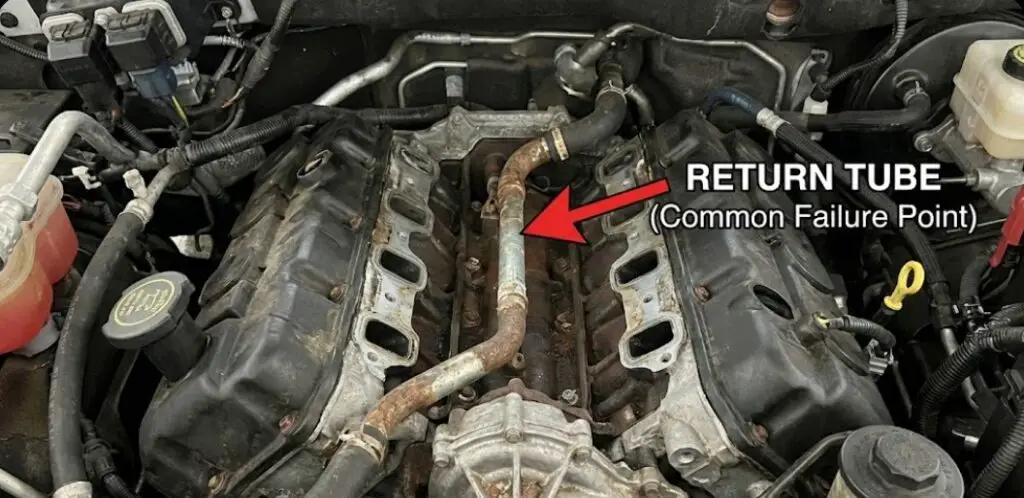
- Termination: The “Heater Tube” (Metal Hardline) in the engine valley.
- Routing: The outlet hose leaves the firewall and connects to a metal tube running under the intake manifold. This tube carries coolant all the way to the back of the water pump housing.
- Identification: If the hose connects to a rusty metal pipe disappearing under the intake, it is the return line.
The “Heater Tube” Failure Mode
The metal return tube running through the engine valley is a notorious leak point.
- Mechanism: Vibration and corrosion cause the O-ring seal at the water pump connection to fail, or the metal tube itself rusts through.
- Symptom: Coolant pools in the valley of the engine block (under the intake), often trickling down the back of the engine and mimicking a rear main seal or head gasket leak.
- Repair Insight: Replacing this tube typically requires removing the intake manifold—a significant labor operation (4–6 hours).
Heater Core Flushing Protocol
Because the heater core is buried deep in the dash (requiring 8+ hours to replace on F-150s), flushing is the first line of defense against poor heat.
- Direction: To flush effectively, you must back-flush. Connect water pressure to the Outlet hose (the one connected to the metal valley tube) and discharge from the Inlet hose (the one from the intake crossover). This reverses the flow, dislodging sediment trapped against the core’s inlet screen.
The 2.3L EcoBoost (2019+ Ranger, Mustang, Focus RS)
Applications: Ford Ranger (T6), Mustang EcoBoost, Focus RS.
System Type: Integrated Turbocharger Cooling Circuit.
The EcoBoost architecture introduces significant complexity: the turbocharger is water-cooled, and its cooling circuit is integrated with the heater core plumbing.
The “Maze” Diagram
The heater hoses on these engines are not simple straight lines; they are branched assemblies.
- Supply (Inlet):
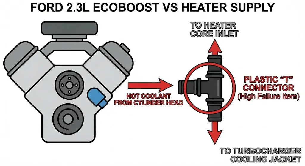
- Origin: Integrated Exhaust Manifold/Head Outlet.
- The Split: A specialized “T” connector (often plastic) splits the hot coolant flow. One branch goes to the heater core inlet, while the other feeds the turbocharger’s water jacket and/or the oil cooler.
- Part Number Ref: Motorcraft KH-series (e.g., CV6Z-18472-AB).
- Return (Outlet):
- Routing: Coolant exits the heater core and merges with the turbocharger return line. This combined flow is routed back to the degas bottle (expansion tank) and the water pump inlet.
The Plastic Tee Failure
The plastic 3-way connector on the heater inlet assembly is a high-failure item. Situated near the hot exhaust/turbo, the plastic becomes brittle and cracks.
- Symptom: Rapid coolant loss and steam from the passenger side of the engine bay.
- Upgrade: Many aftermarket companies now offer aluminum replacement tees to eliminate this weak point, as the factory replacement is the same prone-to-failure plastic.
Bleeding the System
Due to the height of the turbocharger and heater core relative to the engine, air pockets are common. The EcoBoost system relies heavily on the Degas Bottle. The small return hoses from the top of the engine and the heater loop constantly feed air bubbles to the bottle.
- Requirement: The degas bottle must be maintained at the correct level (Max Cold) to ensure there is enough hydrostatic pressure to force coolant into the heater core and turbo lines.
The 4.0L SOHC V6 (Ranger, Explorer)
Applications: 2001–2011 Ranger, Explorer, Mustang.
System Type: Thermostat Housing Hub.
The 4.0L SOHC is infamous for its plastic thermostat housing, which serves as the “Grand Central Station” of coolant flow.
Routing Diagram
- Supply (Inlet):
- Origin: The Thermostat Housing (Top/Front of engine). A molded hose exits this housing and runs to the heater control valve (HCV).
- Control Valve: Unlike the Coyote or Modular engines, the 4.0L often uses a vacuum-actuated HCV inline with the inlet hose. This valve physically stops flow when the A/C is on “Max” to prevent radiant heat from entering the cabin.
- Return (Outlet):
- Termination: Water Pump Bypass or lower thermostat housing port.
- Routing: Returns from the firewall directly to the suction side of the pump.
The Plastic Housing Plague
The thermostat housing consists of two halves glued together. Over time, the glue fails, and the housing cracks.
- Relevance to Heater: The heater supply port is part of this housing. When replacing the housing (a near-certainty for 4.0L owners), technicians often confuse the sensor ports and heater ports. The sensors are retained by clips, while the heater hose is a standard barb or quick connect.
Hardware and Tooling Deep Dive
Understanding the routing is only half the battle; actually disconnecting the hoses on a modern Ford is a distinct challenge due to the proliferation of “Quick-Connect” (QC) fittings.
Taxonomy of Connectors
Ford utilizes several variations of QC fittings, each requiring a different technique.
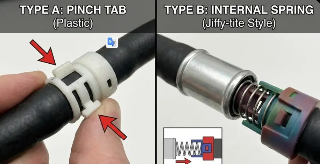
Type A: The “Pinch Tab” (Standard Plastic)
- Visual: A plastic collar (usually white or black) with two visible rectangular tabs protruding from the sides.
- Mechanism: Squeezing the tabs pushes internal plastic ramps away from the metal ridge on the pipe, unlocking the fitting.
- Removal Technique:
- Push the hose forward (toward the engine) to relieve tension on the internal latch.
- Squeeze both tabs firmly with fingers or pliers.
- Pull the hose back while maintaining squeeze pressure.
- Failure: The tabs often snap off due to heat embrittlement. If this happens, the remaining plastic must be carefully cut away with side cutters (dykes) without scoring the metal pipe.
Type B: The “Internal Spring” (Jiffy-tite Style)
- Visual: A smooth barrel connector with no visible tabs, often found on older Fords and some transmission cooler lines.
- Mechanism: A circular garter spring inside the fitting locks behind a ridge on the pipe.
- Tooling: Requires a “Scissor” or “Slide” disconnect tool (e.g., Lisle 39400 or 37500). The tool slides inside the fitting to expand the spring.
Type C: The “Focus/EcoBoost” Clip (Lisle 39200)
- Visual: A specific variation found on the firewall of Focus and Escape models. It is deeply recessed.
- Tooling: The Lisle 39200 tool is specifically designed for this. It is a U-shaped fork that depresses the locking tabs in the tight space against the firewall.
Hose Materials and Degradation
- EPDM (Ethylene Propylene Diene Monomer): The standard material for Ford heater hoses. It is resistant to heat and ozone but susceptible to Electrochemical Degradation (ECD). ECD occurs when the hose and coolant create a battery effect, stripping rubber from the inside of the hose. This creates “striations” or cracks internally, which can lead to pinhole leaks (“spritzers”) near the clamps.
- Silicone: Used in high-performance applications (like HPS kits for Mustangs). Silicone offers superior heat resistance but is more permeable to water vapor, requiring more frequent coolant top-offs.
Replacement Parts Strategy
When a heater hose fails, particularly one with a quick-connect:
- Do Not Repair: Do not attempt to replace just the O-rings inside the QC fitting. The plastic body is likely fatigued.
- Assembly Replacement: Replace the entire hose assembly. For EcoBoost engines, this includes the T-connectors.
- Aftermarket vs. OEM: While Dorman offers replacements (e.g., 800-409 connectors), OEM Motorcraft hoses are preferred for the complex molded shapes of the Coyote and EcoBoost engines to ensure they do not rub against hot exhaust components or pulleys.
Comprehensive Diagnostic & Repair Protocols
Diagnosing “No Heat”
If the blower works but the air is cold:
- Check Coolant Level: Low coolant is the #1 cause. The heater core is high up; if the level drops, it is the first to lose flow.
- Feel the Hoses (The Hand Test):
- Both Hot: Core is getting flow, but blend door actuator inside the dash may be broken (mixing cold air with hot).
- Inlet Hot, Outlet Cold: Flow restriction. Clogged core or clogged restrictor.
- Both Cold: Air lock or total flow failure (water pump impeller failure, stuck thermostat).
The “Gurgle” Fix (Air Bleeding)
A gurgling sound behind the dash indicates air bubbles passing through the core.
- Procedure:
- Elevate: Jack up the front of the vehicle so the degas bottle/radiator cap is the highest point.
- Vacuum Fill: The gold standard. Use an Airlift or similar vacuum filler to evacuate the system and pull coolant in, eliminating air pockets entirely.
- Manual Bleed: If no vacuum tool is available, run the engine at 3,000 RPM for 30 seconds (thermostat open) to surge fluid through the core and push bubbles to the degas bottle.
The Heater Core Flush
If the outlet is cold (clogged core), flushing may save the owner a $1,000+ repair bill.
- Chemicals: Use a radiator flush solvent (like Irontite or Prestone) to break down calcium and rust.
- Method:
- Disconnect both hoses at the firewall.
- Connect a garden hose to the Outlet port.
- Flush backwards (Outlet to Inlet). This pushes the debris out the way it came in, rather than wedging it deeper into the fins.
- Repeat in both directions until water runs clear.
- Critical Step: Blow out the tap water with low-pressure compressed air and fill the core with distilled water or premixed coolant before reconnecting to prevent corrosion from tap water minerals.
Conclusion
The diagram of a heater core system is a map of the engine’s thermal priorities. For the 5.0L Coyote, it reveals a dedication to cylinder head cooling. For the 2.3L EcoBoost, it highlights the integration of turbocharger thermal management. For the 5.4L Triton, it exposes the vulnerability of buried components in the engine valley.
For the technician or enthusiast, successfully navigating these diagrams requires recognizing the difference between a simple hose and a calibrated engineered component. The presence of flow restrictors, the necessity of specific flow directions for air purging, and the fragility of plastic quick-connects transform a simple hose swap into a precision repair. By adhering to the identification protocols—tracing heat signatures, understanding pressure differentials, and respecting the fragility of the hardware—one can ensure that the engine remains cool, the cabin remains warm, and the repair endures the test of time.