Ford F150 Starter Solenoid Wiring Diagram: Easy Setup Guide
The starter solenoid links the battery to the starter motor. A hot wire connects the battery positive to the large common terminal, while a traveler wire from the ignition switch attaches to the small ‘S’ terminal. Ensure the ground wire is secure via the mounting bolts for proper circuit completion.
📌 Key Takeaways
- Visualizes the high-current connection between battery and starter motor
- The ‘S’ terminal traveler wire is essential for triggering the relay
- Always disconnect the negative battery cable before touching solenoid terminals
- Metal-to-metal contact at the fender mounting point acts as the ground
- Essential for diagnosing ‘no-crank’ or ‘click’ starting symptoms
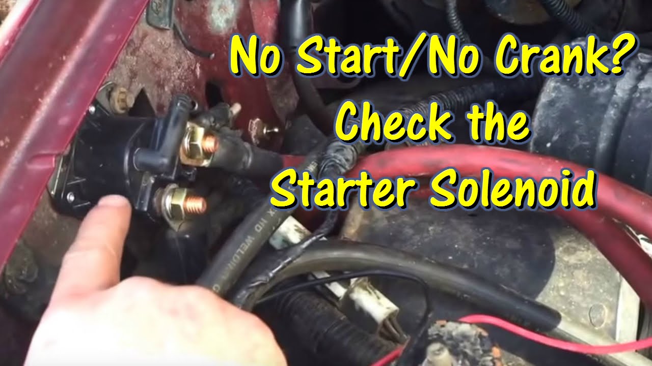
Troubleshooting a non-starting truck can be a frustrating experience, especially when you are dealing with an older classic like the ninth-generation Ford pickups. If you turn your key and hear a sharp “click” or absolutely nothing at all, the culprit is often the fender-mounted relay. Understanding the 1990 ford f150 starter solenoid wiring diagram is essential for any DIY mechanic looking to restore reliable ignition. This guide provides a comprehensive visual and technical breakdown of the electrical connections between your battery, ignition switch, and starter motor, ensuring you can identify every wire color and terminal connection point with precision and confidence.
Understanding the Starter Solenoid Layout
The 1990 Ford F150 utilizes a remote-mounted starter solenoid, typically found on the passenger side inner fender well, near the battery. Unlike many modern vehicles where the solenoid is integrated directly into the starter motor, this vintage Ford design uses the fender-mounted unit as a high-current relay. The diagram consists of three primary connection points and a grounding base that completes the circuit.
At the heart of the 1990 ford f150 starter solenoid wiring diagram are two large threaded studs and one small threaded post. The first large stud, often called the battery side or the “hot” terminal, serves as the central junction for the vehicle’s high-amperage power. It receives the main positive cable from the battery and often hosts several smaller “fusible link” wires that provide power to the alternator and the vehicle’s fuse box. The second large stud is the load side, which sends a massive burst of current directly to the starter motor when engaged.
The small center post, known as the “S” terminal (Start), is the trigger. This is where the ignition signal arrives. When you turn your key to the “Start” position, a 12-volt signal travels through the neutral wire (or neutral safety switch) to this post. This creates an electromagnetic field inside the solenoid, pulling an internal plunger forward to bridge the two large studs and crank the engine.
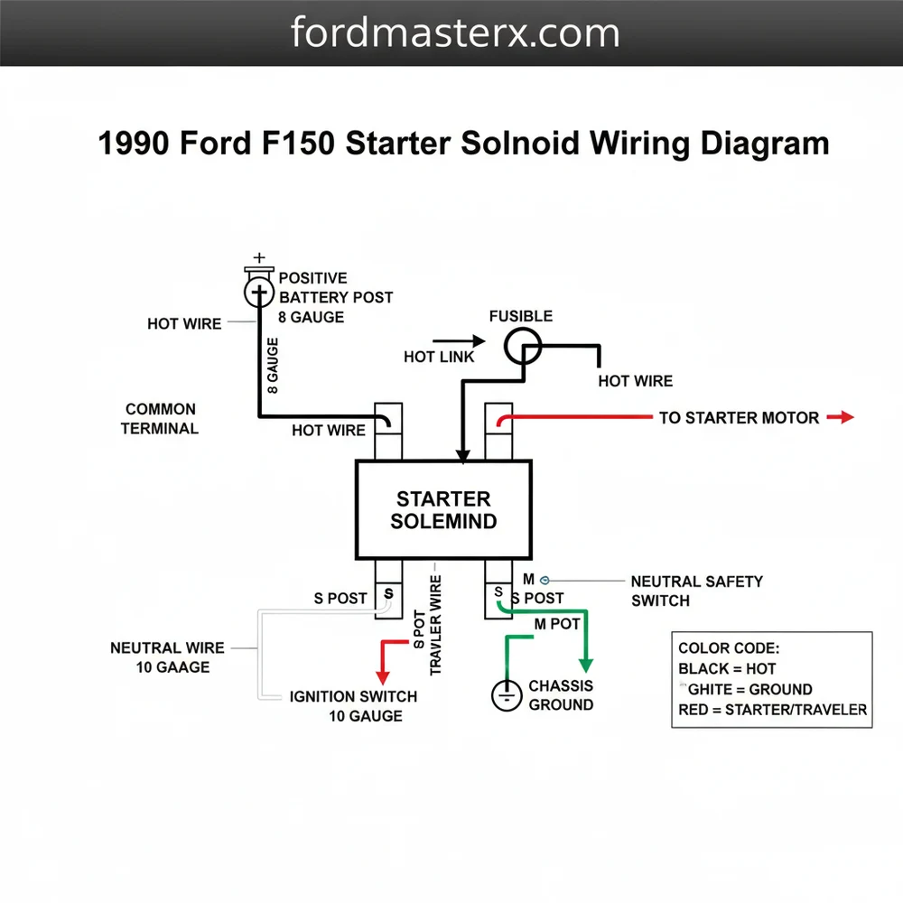
[DIAGRAM_PLACEHOLDER: 1990 Ford F150 Starter Solenoid Wiring Layout]
Terminal A (Left Large Stud): Main Battery Positive (+) Input, 4-Gauge Wire.
Terminal B (Right Large Stud): Starter Motor Output, 4-Gauge Wire.
Terminal S (Small Center Post): Ignition Trigger, Red with Light Blue Stripe.
Mounting Base: System Ground (Must be metal-to-metal contact with fender).
On some 1990 models, you may see an additional ‘I’ terminal. This was used in earlier points-style ignitions to provide a full 12 volts to the coil during cranking. On your 1990 EFI (Electronic Fuel Injection) truck, this post is often present on replacement solenoids but is usually left disconnected.
Step-by-Step Installation and Wiring Guide

Following a 1990 ford f150 starter solenoid wiring diagram requires a methodical approach to ensure safety and electrical integrity. If the wires are crossed or the connections are loose, you risk melting your wire harness or causing a battery explosion.
- ✓ Step 1: Disconnect the Battery: Before touching any terminal, disconnect the negative battery cable. This prevents accidental shorting of the hot wire against the chassis while you work.
- ✓ Step 2: Clean the Mounting Surface: The solenoid grounds through its metal mounting bracket. Use sandpaper to clean the fender area to ensure a solid ground wire connection through the mounting bolts.
- ✓ Step 3: Connect the Starter Cable: Attach the heavy-gauge wire leading down to the starter to the right-side brass screw terminal. Tighten until snug, but do not over-torque, as the internal plastic housing can crack.
- ✓ Step 4: Identify the Trigger Wire: Locate the thin Red/Light Blue wire. This is your “traveler wire” from the ignition. Press or screw it onto the small “S” terminal in the center.
- ✓ Step 5: Connect the Main Power: Place the thick positive battery cable and any smaller accessory eyelets (fusible links) onto the left-side common terminal. This is the main “hot wire” junction for the engine bay.
- ✓ Step 6: Final Verification: Reconnect the negative battery cable and test for voltage at the battery side terminal using a multimeter.
Never bridge the two large terminals with a screwdriver unless you are in an emergency diagnostic situation. Doing so creates massive sparks and can weld the tool to the terminals or cause the battery to discharge violently.
Common Issues and Troubleshooting
Even with a perfect 1990 ford f150 starter solenoid wiring diagram, components can fail over time due to heat, vibration, and corrosion. One of the most common issues is a “click” sound but no engine rotation. This usually indicates that the internal copper disc inside the solenoid has become pitted or carbon-tracked, preventing it from passing enough voltage to the starter motor.
Another frequent problem is the “stuck” solenoid, where the starter continues to spin even after you release the key. This happens when the internal contact disc welds itself to the brass screw terminals. In this scenario, you must quickly disconnect the battery to prevent the starter motor from burning out or the battery from draining completely.
If you have no power at all when turning the key, check the neutral wire circuit. For automatic transmissions, the Neutral Safety Switch (NSS) on the side of the transmission must be engaged. For manual trucks, the Clutch Pedal Position (CPP) switch must be fully depressed. If these switches fail, the 12V signal will never reach the “S” terminal on your solenoid.
Tips and Best Practices for Maintenance
To ensure your 1990 Ford F150 stays reliable, pay close attention to the gauge of the wires used. The main battery and starter cables should be at least 4-gauge, though 2-gauge is often preferred for colder climates where the engine requires more torque to turn over. Undersized wires will create resistance, dropping the voltage and causing the solenoid to chatter or fail prematurely.
Apply a small amount of dielectric grease to all terminal connections before tightening the nuts. This prevents moisture from causing corrosion between the copper eyelet and the brass terminal, which is the leading cause of “slow crank” issues in older Ford trucks.
Maintenance recommendations also include checking the fusible links attached to the battery-side terminal of the solenoid. These links are designed to melt and break the circuit if there is a major short in the alternator or headlight circuit. If your truck has no interior lights and no dash power, look for a “rubbery” feeling wire near the solenoid; if it stretches like a rubber band, the internal wire has melted, and the link must be replaced.
When purchasing a replacement, avoid the cheapest generic options. Look for a heavy-duty solenoid with high-quality copper internals. Lower-quality units often use thinner metal for the internal contact disc, leading to a much shorter lifespan under the high-heat conditions of an F150 engine bay. By following this 1990 ford f150 starter solenoid wiring diagram and keeping your connections clean and tight, you can ensure your truck starts on the first turn of the key every single time.
Frequently Asked Questions
Where is the starter solenoid located?
On a 1990 Ford F150, the starter solenoid is mounted directly to the passenger-side inner fender well, just behind the battery. This external mounting is a classic Ford design, making it much easier to access, test, or replace compared to solenoids mounted directly on the starter motor beneath the truck.
What does this wiring diagram show?
This diagram illustrates the electrical path from the battery to the starter. It highlights the hot wire providing constant power, the traveler wire sending the start signal from the ignition, and how the solenoid acts as a heavy-duty switch to bridge the high-amperage gap required to crank the engine.
How many connections does the solenoid have?
The solenoid typically features four points of contact. There are two large threaded studs: one common terminal for the battery and accessories, and one for the starter cable. Additionally, there is a small ‘S’ terminal for the ignition traveler wire and occasionally an ‘I’ terminal for the ignition coil.
What are the symptoms of a bad solenoid?
Common symptoms include a single loud click when turning the key, rapid clicking, or absolutely no sound at all. If the ground wire connection through the fender is corroded, the solenoid may fail to engage. Sometimes, the internal contacts weld together, causing the starter to stay engaged continuously.
Can I replace this myself?
Yes, replacing the starter solenoid is one of the easiest DIY tasks on an older F150. Since it is located on the fender wall, you do not need to jack up the vehicle. By following the wiring diagram, you can swap the unit in under twenty minutes using basic wrenches.
What tools do I need for this task?
You will need a basic socket set or open-ended wrenches, typically 5/16″, 1/2″, and 9/16″. A wire brush is highly recommended to clean the common terminal and ground wire contact points. A multimeter or test light is also helpful for verifying that the hot wire has constant voltage.