Ford F150 Oxygen Sensor Location: Quick Identification Guide
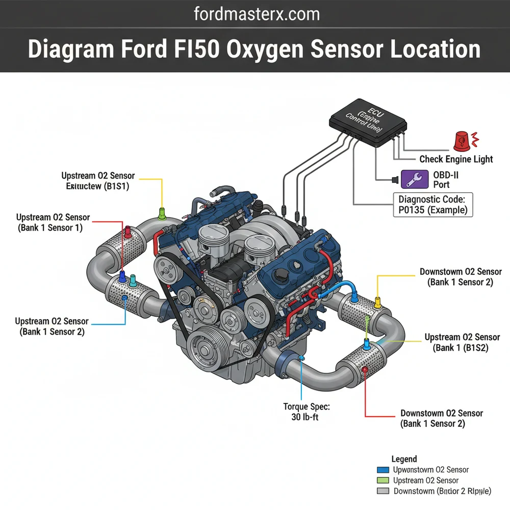
The Ford F150 oxygen sensors are located in the exhaust stream. Bank 1 is on the passenger side, and Bank 2 is on the driver side. Upstream sensors (Sensor 1) sit before the catalytic converter, while downstream sensors (Sensor 2) are located after it, sending vital exhaust data back to the vehicle’s ECU.
📌 Key Takeaways
- The diagram identifies the four primary oxygen sensor positions on V-engine models
- Distinguishing between upstream (Sensor 1) and downstream (Sensor 2) is critical for repairs
- Always allow the exhaust system to cool completely to avoid severe burn injuries
- Use a specialized O2 sensor socket to prevent stripping the sensor body or threads
- Refer to this diagram whenever an OBD-II scanner reports a specific bank-related error
Navigating the exhaust system of a modern truck requires precision and patience, which is why having an accurate diagram ford f150 oxygen sensor location guide is essential for any successful DIY repair or diagnosis. When your vehicle triggers a warning, the complexity of the engine bay can be overwhelming without a clear roadmap. This guide provides a visual and descriptive breakdown of the sensor placements across the most common Ford F-150 engine configurations. By understanding the specific orientation of Bank 1 versus Bank 2, and the functional difference between upstream and downstream sensors, you will be equipped to clear diagnostic codes and restore your truck’s performance efficiently.
Most Ford F-150 models utilize a four-sensor system. Bank 1 always refers to the side of the engine containing cylinder number one (typically the passenger side on Ford V8 and V6 engines), while Bank 2 refers to the driver side.
Decoding the Oxygen Sensor Layout Diagram
The oxygen sensor system in a Ford F-150 is strategically mapped to monitor the efficiency of the combustion process and the health of the catalytic converters. To read a location diagram correctly, you must first orient yourself from the driver’s seat perspective. In a standard V-configuration engine, such as the 5.0L V8 or the 3.5L EcoBoost, the diagram will show two distinct “Banks.”
Bank 1 is located on the passenger side of the vehicle. Within this bank, there are two sensors. Sensor 1, often called the “upstream” sensor, is positioned in the exhaust manifold or the pipe lead-in before the catalytic converter. This sensor is the primary data source for the ECU (Engine Control Unit) to adjust the air-fuel mixture. Sensor 2, the “downstream” sensor, is located immediately after the catalytic converter to monitor its scrubbing efficiency.
Bank 2 is located on the driver side. Like Bank 1, it features a Sensor 1 (upstream) and a Sensor 2 (downstream). The diagram visually separates these by the transmission tunnel. Landmark references are crucial here: the upstream sensors are generally found near the rear of the engine block, often close to the firewall, whereas the downstream sensors are visible from under the center of the truck, protruding from the exhaust pipe after the large bulbous catalytic converter units.
Note: This diagram illustrates the exhaust flow from the engine manifolds, past the upstream sensors (B1S1, B2S1), through the catalytic converters, and finally past the downstream sensors (B1S2, B2S2) toward the muffler.
Variations may occur in specific heavy-duty or specialized emissions packages, but the standard four-sensor layout remains the most frequent configuration. The wiring harnesses are often color-coded or keyed differently to prevent plugging a downstream sensor into an upstream connector, though the physical location remains the most reliable way to identify which sensor is failing based on your OBD-II scanner’s output.
Step-by-Step Guide to Locating and Accessing Sensors

To accurately use the diagram ford f150 oxygen sensor location data for a repair, follow these systematic steps. These steps ensure you are looking at the right component before you begin the labor-intensive process of removal.
- ✓ Step 1: Identify the Faulty Bank – Use an OBD-II scanner to pull the specific diagnostic code. A code like P0171 points to Bank 1, while P0174 points to Bank 2. Knowing this saves you from inspecting the wrong side of the engine.
- ✓ Step 2: Locate Bank 1 (Passenger Side) – Open the hood and find the side of the engine that sits further forward toward the accessory belt. In Fords, the passenger side cylinder head usually sits slightly ahead of the driver side, confirming it as Bank 1.
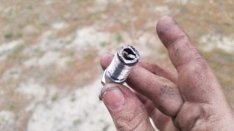
- ✓ Step 3: Access Upstream Sensors (Sensor 1) – These are best accessed through the wheel wells. You may need to remove the plastic inner fender liner to get a clear line of sight to the exhaust manifold. Look for the sensor threaded into the pipe before it reaches the catalytic converter.
- ✓ Step 4: Access Downstream Sensors (Sensor 2) – Slide under the vehicle near the transmission. Follow the exhaust pipe back from the engine. You will see the catalytic converter (a large metal canister). The downstream sensor is located in the pipe directly behind this canister.
- ✓ Step 5: Trace the Wiring – Before removing the sensor, trace the wire back to the plastic electrical connector. These are often clipped to the transmission housing or the frame rail. Ensure the clip is not melted or damaged.
- ✓ Step 6: Use Specialized Tools – An oxygen sensor socket (which has a slit for the wire) is highly recommended. Because these sensors are exposed to extreme heat cycles, they often “seize” into the exhaust pipe.
- ✓ Step 7: Verification – Once the new sensor is in place, clear the codes and perform a drive cycle. This allows the ECU to relearn the exhaust values.
Never attempt to locate or replace oxygen sensors while the engine is hot. Exhaust temperatures can exceed 1,000 degrees Fahrenheit, and even a brief touch can cause severe burns. Allow the vehicle to cool for at least two hours.
Common Issues and Troubleshooting

The most frequent reason users search for the diagram ford f150 oxygen sensor location is the sudden appearance of a check engine light. Oxygen sensors are wear items, but their failure can often be a symptom of a deeper mechanical issue. For example, if you see a sensor code alongside a warning about coolant flow, you might have a leaking head gasket. Contamination from coolant or excess engine oil will “poison” the sensor, coating the internal ceramic element and making it unresponsive.
Another common issue involves the ECU receiving erratic signals. This doesn’t always mean the sensor is bad; sometimes, the wiring harness has rubbed against the accessory belt or a sharp heat shield, causing a short circuit. If the diagram shows the sensor is in a tight spot near the timing chain cover or manifold, check for heat-related wire degradation. If your scanner shows a “slow response” code, the sensor is likely fouled with carbon and needs replacement rather than just a wiring fix.
Tips and Best Practices for Long-Term Maintenance
To ensure your F-150 runs efficiently and avoids premature sensor failure, follow these pro tips. First, always use high-quality, OEM-spec sensors. Cheap aftermarket sensors often have different resistance levels that the Ford ECU may reject, leading to a persistent check engine light even after replacement.
Apply a small amount of high-temperature anti-seize to the threads of the new sensor, but be extremely careful not to get any on the sensor’s perforated tip. This ensures you can remove it easily in the future without damaging the exhaust pipe threads.
When installing the new component, adhere to the proper torque spec, which is typically around 30 lb-ft (40 Nm) for most Ford sensors. Over-tightening can crack the ceramic heater element inside the sensor, rendering it useless before you even start the engine. Additionally, check your air filter and intake system; a vacuum leak can cause the sensors to report a “lean” condition, leading you to replace a perfectly good sensor when the real culprit is a cracked rubber hose.
Finally, keep an eye on your OBD-II live data if you have a capable scanner. Watching the voltage switch rapidly between 0.1V and 0.9V on your upstream sensors is the best way to confirm they are healthy. Downstream sensors should remain relatively steady. If you notice a steady drop in fuel economy, consult your diagram ford f150 oxygen sensor location guide and consider a proactive replacement if your truck has exceeded 100,000 miles, as sensors naturally degrade over time even without triggering a hard code.
Frequently Asked Questions
Where is the Ford F150 oxygen sensor located?
Most Ford F150 models feature four sensors. Bank 1 is on the passenger side, and Bank 2 is on the driver side. Sensor 1 (upstream) is located between the engine and catalytic converter, while Sensor 2 (downstream) is positioned behind the converter to monitor its cleaning efficiency.
What does the oxygen sensor diagram show?
The diagram illustrates the specific positioning of upstream and downstream O2 sensors within the exhaust manifold and piping. It helps DIYers distinguish between Bank 1 and Bank 2, ensuring the correct sensor is replaced based on the specific diagnostic code provided by the OBD-II scanner.
How many wires does a Ford F150 oxygen sensor have?
Most modern F150 oxygen sensors use a four-wire configuration. This typically includes two wires for the internal heater element, one signal wire to communicate with the ECU, and one ground wire. Always verify your specific connector type before purchasing a replacement to ensure a proper plug-and-play fit.
What are the symptoms of a bad oxygen sensor?
Common symptoms include a persistent check engine light, decreased fuel economy, and a rough idle. If the ECU receives incorrect data, it may cause the engine to run too rich or lean. You might also notice a ‘rotten egg’ smell or fail an emissions test.
Can I replace the oxygen sensor myself?
Yes, replacing an oxygen sensor is a common DIY task. While access can be tight depending on the engine size, most sensors are accessible from under the truck. You will need a floor jack, jack stands, and potentially penetrating oil to loosen sensors that have rusted into the exhaust pipe.
What tools do I need for oxygen sensor replacement?
You will need a 22mm or 7/8-inch oxygen sensor socket, a ratchet or breaker bar, and an OBD-II scanner to clear codes. Using a torque spec of approximately 30 lb-ft is recommended during installation. Don’t forget anti-seize lubricant for the threads to make future removals easier.