Ford F150 Heater Hose Diagram: Visual Layout Guide
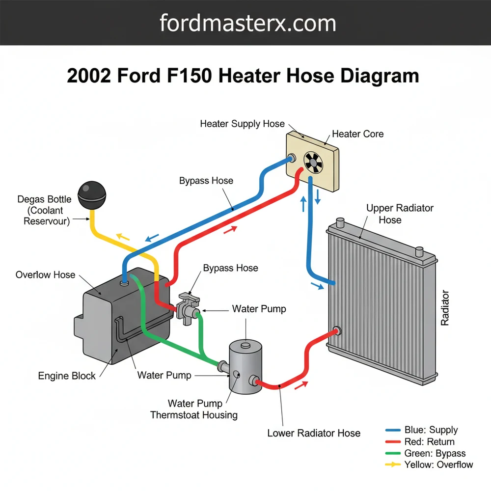
The 2002 Ford F150 heater hose diagram illustrates the routing between the water pump, engine block, and heater core. It features an inlet hose carrying hot coolant to the core and a return hose leading back to the cooling system. This configuration ensures proper cabin heating and engine temperature regulation.
📌 Key Takeaways
- Main purpose of this diagram is to visualize the coolant path between the engine and heater core.
- The most important components to identify are the supply and return hoses at the firewall.
- Always ensure the engine is cold before touching the pressurized cooling system.
- Use this diagram to find leaks or collapsed hoses that cause cabin heating loss.
- Essential for accurately replacing quick-disconnect fittings or heater core components.
Navigating the engine bay of a classic light-duty truck requires more than just mechanical intuition; it demands a precise roadmap to avoid costly errors. When you are performing maintenance on the cooling system, having a reliable 2002 ford f150 heater hose diagram is the difference between a quick afternoon fix and a multi-day project. This visual guide serves as a critical resource for identifying the complex routing of coolant between the engine block and the heater core. By understanding the specific layout of these hoses, you can effectively diagnose leaks, replace worn components, and ensure your cabin remains warm during the winter months. In this comprehensive overview, you will learn how to identify every hose, interpret the routing schematics, and apply this knowledge to your DIY repairs with confidence.
The 2002 Ford F150 utilizes different heater hose configurations depending on whether the vehicle is equipped with the 4.2L V6, the 4.6L V8, or the 5.4L V8 Triton engine. Always verify your engine displacement before purchasing replacement parts.
Understanding the 2002 Ford F150 Heater Hose Diagram Layout
The heater hose system in a 2002 Ford F150 is a closed-loop configuration designed to transport hot engine coolant to the heater core located inside the dashboard. The blueprint of this system typically consists of two primary lines: the supply (inlet) hose and the return (outlet) hose. While the fundamental structure remains consistent across the F150 lineup, the physical layout and the attachment points vary significantly based on the engine type. On the 4.6L and 5.4L V8 engines, the hoses are often routed across the passenger side of the engine, whereas the V6 models may feature a more centralized configuration.
A standard 2002 ford f150 heater hose diagram labels the components using a mix of numeric codes and color-coded paths. The supply line is usually depicted in red or a solid line, indicating the flow of high-temperature coolant from the intake manifold or the cylinder head to the heater core. Conversely, the return line is often shown in blue or a dashed line, representing the slightly cooler liquid returning to the water pump or the engine block to be reheated. Key components illustrated in the schematic include the heater core nipples at the firewall, the quick-connect fittings, the hose clamps, and any bypass valves that might be present in specialized towing packages.
One of the most distinctive elements of the Ford F150 hose layout is the use of plastic quick-connectors at the firewall. These are specialized fittings designed to snap onto the heater core tubes without the need for traditional worm-gear clamps. The diagram will highlight these as specific junction points. Furthermore, for those with the 5.4L Triton engine, the layout may include a “spider” assembly or a “Y” pipe configuration that splits the coolant flow to provide thermal management for other components, such as the throttle body or the PCV system. Understanding this schematic layout prevents the common mistake of crossing the inlet and outlet lines, which can lead to inefficient heating performance.
[DIAGRAM_PLACEHOLDER – A detailed technical schematic showing the 2002 Ford F150 engine bay from a top-down perspective, highlighting the red inlet hose from the intake manifold to the firewall and the blue return hose from the firewall to the water pump/timing cover area.]
Step-by-Step Guide to Interpreting and Utilizing the Diagram

Reading a technical schematic can be intimidating for beginners, but it is a vital skill for any Ford truck owner. To properly use the 2002 ford f150 heater hose diagram for a repair or inspection, follow this structured approach to ensure accuracy and safety.
- ✓ Step 1: Orient Your Perspective: Stand at the front of the vehicle looking toward the windshield. The diagram is usually drawn from this “top-down” bird’s eye view. Identify the firewall (the metal partition between the engine and the cabin) as your primary reference point.
- ✓ Step 2: Identify the Firewall Connections: Locate the two aluminum tubes protruding from the passenger side of the firewall. These are the heater core inlet and outlet. On the diagram, these are the termination points for both hoses.
- ✓ Step 3: Trace the Supply Line: Following the blueprint, trace the hose that connects to the engine’s intake manifold (usually near the front on V8 models). This hose carries the hottest coolant. Note the routing path—it often tucks under the air intake assembly to avoid moving parts.
- ✓ Step 4: Trace the Return Line: The second hose on the firewall connects back to the water pump or the timing cover. This path completes the loop. In the diagram, look for the hose that leads toward the lower section of the engine bay.
- ✓ Step 5: Locate Junctions and Brackets: The schematic will show plastic clips or metal brackets that hold the hoses in place. These are essential for preventing the hoses from rubbing against the exhaust manifold or vibrating against the frame.
- ✓ Step 6: Prepare Your Tools: Based on the diagram’s connection points, you will likely need a heater hose disconnect tool (for the quick-connect fittings), pliers for the constant-tension clamps, and a drain pan to catch the coolant.
Never attempt to disconnect or inspect heater hoses while the engine is hot. The cooling system is under high pressure, and escaping steam or boiling coolant can cause severe burns. Allow the vehicle to cool for at least two hours before beginning work.
When you are actually performing the replacement, use the diagram to verify that you haven’t twisted the hoses. A kinked heater hose will restrict coolant flow, resulting in poor heater performance and potentially causing the engine to run hotter than normal. If your F150 has been modified or has an aftermarket cooling system, the diagram serves as a baseline to restore the system to its original, factory-intended configuration.
Common Issues and Troubleshooting with Heater Hoses

The heater hose system on the 2002 Ford F150 is robust, but age and heat cycles eventually take their toll. One of the most frequent problems is the failure of the plastic quick-connect fittings at the firewall. Over time, these plastic components become brittle and develop hairline cracks, leading to slow coolant loss that can be difficult to track down without a blueprint of the system. If you notice a sweet smell inside the cabin or see “steam” coming from the back of the engine, the diagram will help you pinpoint whether the leak is at the hose-to-firewall junction or the heater core itself.
Another common issue is hose “collapsing” or “softening.” Because these hoses are made of rubber, oil contamination or simple age can cause the inner structure to break down. A hose that looks fine on the outside might collapse internally under the suction of the water pump, cutting off heat to the cabin. By using the 2002 ford f150 heater hose diagram, you can identify which section of the hose is the most likely culprit based on its proximity to high-heat zones like the exhaust manifolds. Furthermore, if you experience a “gurgling” sound behind the dashboard, it usually indicates air trapped in the heater core. The schematic layout helps you understand how to properly “burp” the system by identifying the highest point in the cooling loop.
If you are replacing one heater hose, it is highly recommended to replace both. Since they are exposed to the same heat and pressure, the second hose is likely to fail shortly after the first. Buying them as a set also ensures the fittings match.
Maintenance Tips and Best Practices
To maximize the lifespan of your cooling system and ensure the accuracy of your 2002 ford f150 heater hose diagram during future repairs, follow these maintenance best practices. First, always use the correct coolant type specified in your owner’s manual—typically Premium Gold or Green coolant for this era of Ford trucks. Mixing incompatible coolants can lead to “sludge” buildup, which clogs the narrow passages of the heater core and the hoses, rendering your schematic-based troubleshooting much more difficult.
When installing new hoses, pay close attention to the clamping mechanism. While many DIYers prefer traditional worm-gear clamps, the original spring-style (constant tension) clamps are often better at handling the expansion and contraction of the rubber as temperatures fluctuate. Ensure the hose is seated fully past the “bead” on the metal pipe before securing the clamp. Referencing your layout guide, make sure all protective sleeves or heat shields are transferred from the old hoses to the new ones; these are critical for protecting the rubber from the intense heat of the Triton V8 engines.
Finally, consider the quality of your components. While generic bulk hose is cheaper, molded hoses that match the exact configuration of the 2002 ford f150 heater hose diagram are superior. Molded hoses are pre-bent to fit the tight clearances of the engine bay without kinking. This ensures that the system maintains its structural integrity and flow rate. Regular inspections every 30,000 miles for signs of bulging, cracking, or “sponginess” can prevent a roadside breakdown and keep your truck’s cooling system operating at peak efficiency for years to come.
In conclusion, the 2002 ford f150 heater hose diagram is an indispensable asset for any truck owner looking to maintain their vehicle’s performance. By providing a clear overview of the system configuration, from the intake manifold to the heater core, this guide allows for precise identification and repair of cooling components. Whether you are dealing with a minor leak at a quick-connect fitting or performing a total system overhaul, adhering to the blueprint ensures a professional-grade result. With the right tools, a bit of patience, and a clear understanding of the hose layout, you can keep your F150 running cool and your cabin warm, regardless of the weather outside.
Frequently Asked Questions
Where is the heater hose located?
The heater hoses on a 2002 Ford F150 are located at the rear of the engine compartment. They connect the engine’s intake manifold and water pump to the heater core ports protruding through the passenger side of the firewall. Identifying this location is the first step for any cooling system repair.
What does this heater hose diagram show?
This diagram shows the specific routing and configuration of the heater supply and return lines. It illustrates the layout from the engine’s heat source to the cabin’s heater core, helping owners identify every component and connection point within the pressurized cooling system to ensure efficient heat transfer.
How many connections does the heater hose system have?
Most 2002 Ford F150 heater hose systems utilize two primary connections: an inlet hose and an outlet hose. Depending on the specific engine configuration, these hoses may use standard worm-gear clamps or specialized plastic quick-disconnect fittings that snap onto the heater core’s aluminum tubes at the firewall.
What are the symptoms of a bad heater hose?
Common symptoms of a failing heater hose include visible coolant puddles under the truck, a sweet smell inside the cabin, or steam rising from the engine bay. Additionally, if the hoses are soft or bulging, the system may lose pressure, leading to poor heater performance and engine overheating.
Can I replace the heater hoses myself?
Replacing heater hoses is a manageable DIY task for most owners. However, accessing the firewall connections can be tight, and Ford’s quick-disconnect fittings often require a specific removal tool. Always ensure the engine is completely cool before starting to avoid severe burns from the pressurized coolant system.
What tools do I need for heater hose replacement?
To work on the heater hose system, you will need a drain pan for coolant, needle-nose pliers for clamps, and potentially a quick-disconnect tool. A screwdriver is helpful for worm-gear clamps, and having fresh 50/50 prediluted coolant ready for the refill and air-bleeding process is essential.