Ford F150 Fuel Pump Wiring Diagram: Easy Setup Guide
The fuel pump circuit utilizes a hot wire to carry voltage from the battery through the relay and inertia switch to the pump. By identifying the common terminal on the relay, you can trace power flow. The circuit is completed by a ground wire, which returns current to the vehicle chassis.
📌 Key Takeaways
- Identify the color-coded power and ground paths
- Locate the inertia switch as a common point of failure
- Always disconnect the battery before testing wiring
- Use a multimeter to check for 12V at the pump connector
- Necessary for diagnosing ‘crank but no start’ conditions
The 1995 Ford F-150 remains a staple of the “Old Body Style” (OBS) enthusiasts. Known for its ruggedness and the longevity of its engines—ranging from the legendary 4.9L inline-six to the 5.0L and 5.8L V8s—it is a vehicle built to last. However, as these trucks age, the electrical systems, particularly the fuel delivery circuit, can become a point of failure. Understanding the 1995 Ford F-150 fuel pump wiring diagram is not just a matter of academic interest; it is a critical skill for any DIY owner looking to diagnose a “crank-no-start” condition. Because these trucks often featured dual fuel tanks, the wiring is slightly more complex than a standard single-tank vehicle, involving a selector switch, an inertia safety switch, and specific relay triggers from the Powertrain Control Module (PCM).
Main Components and System Features
The fuel delivery system in a 1995 F-150 is managed by the EEC-IV (Electronic Engine Control) system. To effectively use a wiring diagram, you must first identify the key players in the circuit. Each component serves as a potential “point of failure” that can interrupt the flow of electricity to the pump.
- Powertrain Control Module (PCM): The “brain” of the truck. It provides the ground signal to the fuel pump relay to prime the system for two seconds when the key is first turned to “On,” and then continuously once it detects an RPM signal from the distributor.
- Fuel Pump Relay: Located in the Power Distribution Box (the fuse box under the hood, usually on the driver-side fender). This relay takes a small signal from the PCM to close a high-current circuit that powers the pumps.
- Inertia Fuel Shut-off Switch: A safety device designed to cut power to the fuel pumps in the event of a collision. In the 1995 model, it is typically located inside the cab, on the passenger side kick panel or just above it.
- Dual Tank Selector Switch: Found on the dashboard, this switch toggles power between the front (mid-ship) and rear (aft-axle) fuel pumps. It also switches the fuel gauge sending unit signal so the dashboard reflects the level of the tank currently in use.
- In-Tank Fuel Pump Assemblies: Each tank contains its own high-pressure pump, a fuel level sending unit, and a sock-type filter. These are the final destinations for the electrical current.
How to Use and Read the Wiring Diagram

Reading a Ford wiring diagram requires tracing the path of power from the battery to the ground. In the 1995 F-150, the circuit follows a specific hierarchy. If you lose power at any point in this chain, the pump will not run.
1. The Power Source: Power begins at the battery and travels through a high-current fuse (usually a 20A or 30A Maxi-fuse) in the under-hood Power Distribution Box. This wire is typically Yellow or Dark Green/Yellow and provides constant power to Pin 30 of the fuel pump relay.
2. The Relay Trigger: When you turn the key, the PCM sends power to the relay coil (Pin 85) via a Red wire. Simultaneously, the PCM grounds the other side of the coil (Pin 86) using a Tan/Light Green wire. This creates a magnetic field that closes the relay.
3. From Relay to Inertia Switch: Once the relay closes, power exits the relay (Pin 87) on a Dark Green/Yellow wire. This wire travels through the firewall to the Inertia Switch. If the switch hasn’t been tripped, the power exits the switch on a Pink/Black wire.
4. The Selector Switch: The Pink/Black wire enters the back of the dash-mounted tank selector switch. Depending on the switch position:
- Front Tank: Power exits the switch on a Red/Yellow wire leading to the front pump.
- Rear Tank: Power exits the switch on a Brown/White wire leading to the rear pump.
5. Grounds: Every pump needs a ground to complete the circuit. The ground wires for the pumps are almost always solid Black. These are usually grounded to the frame rail near the tanks or at a common ground point on the radiator support.
Practical Tips for DIY Enthusiasts

When working with 1995 F-150 wiring, the environment is your biggest enemy. These trucks are decades old, and the wiring harnesses are exposed to road salt, moisture, and heat. Here are some practical tips for handling the hardware:
- Accessing the Pumps: Many DIYers prefer to unbolt the six or eight bolts holding the truck bed and slide it back or tilt it up rather than dropping the tanks. This gives you clear, top-down access to the wiring connectors at the top of the tanks, which are notoriously difficult to reach when the tank is strapped to the frame.
- Wire Identification: Over time, wire colors fade. Use a damp rag to clean a section of the wire to reveal its true color and stripe. A “Pink/Black” wire is a pink wire with a thin black longitudinal stripe.
- Connector Corrosion: The round plastic connectors at the fuel pump assembly are prone to melting or corroding. If you see signs of “greening” (copper oxidation) or charred plastic, the connector itself is likely causing high resistance, which can burn out a new pump.
- Voltage Drop Testing: Don’t just check for “12 volts.” Use a multimeter to perform a voltage drop test. A wire might show 12V with no load, but fail to carry the amperage needed to turn the pump under load. You should see less than a 0.5V drop between the battery positive and the pump connector while the circuit is active.
Troubleshooting Common Wiring Issues
If your 1995 F-150 won’t start and you suspect the fuel pump, follow this logical troubleshooting sequence based on the wiring diagram logic:
Step 1: The “Priming” Test
Cycle the key to the “On” position (don’t crank). You should hear a faint “whir” for two seconds. If you hear nothing, the circuit is broken. If you hear it on one tank but not the other, the problem is likely the selector switch or the specific pump/wiring for that tank.
Step 2: Check the Inertia Switch
This is the most common “easy fix.” If you hit a large pothole or someone bumped your truck, the button on top of the inertia switch may have popped up. Push it down to reset it. Use a multimeter to check for 12V on both the Dark Green/Yellow (input) and Pink/Black (output) wires while a friend cycles the key.
Step 3: Test the Relay
Swap the fuel pump relay with a known good relay in the fuse box (like the horn relay, if compatible). If the truck starts, you’ve found your culprit. You can also “jump” Pins 30 and 87 in the relay socket with a fused jumper wire; if the pump stays on constantly, the wiring from the relay to the pump is good, and the problem lies in the relay or the PCM’s trigger signal.
Step 4: Inspect the Selector Switch
The dash switch is a high-failure item. If the internal contacts fail, no power will reach either pump. You can bypass the switch by jumping the Pink/Black wire directly to the Red/Yellow (front) or Brown/White (rear) wires behind the dashboard. If the pump kicks on, replace the switch.
Step 5: Verify the Ground
Ford trucks of this era often suffer from “bad grounds.” Locate the black wire at the fuel pump connector. Use a multimeter to check continuity between this wire and a clean spot on the vehicle frame. If the resistance is high (over 5 ohms), the pump will not have enough “pull” to operate correctly. Cleaning the ground eyelet on the frame with sandpaper often solves mysterious intermittent fuel issues.
By systematically following the wiring path—from the Power Distribution Box to the Inertia Switch, through the Selector Switch, and down to the tanks—you can diagnose even the most stubborn fuel delivery problems. The 1995 Ford F-150 is a logical, serviceable machine, and with a multimeter and a basic understanding of its wiring colors, you can keep it on the road for many more years.
Step-by-Step Guide to Understanding the Ford F150 Fuel Pump Wiring Diagram: Easy Setup Guide
Identify the power distribution box and locate the fuel pump relay.
Locate the inertia switch behind the passenger-side kick panel.
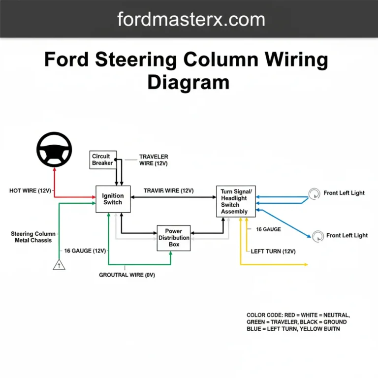
Understand how the traveler wire moves current from the relay to the inertia switch.
Connect a multimeter to the common terminal to verify if the relay is engaging.
Verify that the neutral wire or ground wire has a clean, rust-free connection to the frame.
Complete the inspection by testing for 12V at the fuel pump harness connector.
Frequently Asked Questions
Where is the fuel pump located?
The fuel pump is located inside the fuel tank. If your truck has dual tanks, there is an individual pump inside each one. You can access the wiring and the pump itself either by carefully lowering the fuel tank or by removing the truck bed to reach the top of the tanks.
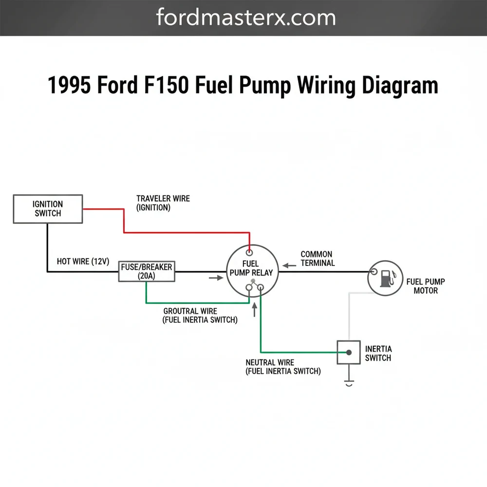
What does this wiring diagram show?
This diagram illustrates the electrical path from the battery and ignition switch to the fuel pump relay, inertia switch, and the pump motor. It helps users trace the hot wire and ground connections to ensure the pump receives the necessary voltage and current to prime the engine and maintain fuel pressure.
How many wires does the fuel pump have?
The fuel pump assembly typically uses a four-wire connector. This includes the hot wire for power, a dedicated ground wire to complete the circuit, and two additional wires for the fuel level sending unit. Knowing these connections is essential for diagnosing both fuel delivery issues and inaccurate fuel gauge readings.
What are the symptoms of a bad fuel pump?
Common symptoms include the engine cranking but failing to start, significant power loss under load, or sputtering at high speeds. If you do not hear the pump whine for a few seconds when the key is turned to the ‘on’ position, there is likely a break in the electrical circuit.
Can I replace the wiring myself?
Yes, a DIYer can replace or repair the wiring using this diagram and basic electrical tools. While dropping the tank is labor-intensive, the wiring work involves simple splicing or connector replacement. Ensure all connections are weather-sealed to prevent corrosion, which is a common cause of electrical failure in older trucks.
What tools do I need for this task?
To properly use this wiring diagram, you will need a digital multimeter or a test light to check for voltage. Additionally, a socket set is required to access the relay box or fuel tank, and wire strippers/crimpers are necessary if you need to repair any damaged sections of the harness.