Ford F150 Brake Lines Diagram: Easy Routing Guide
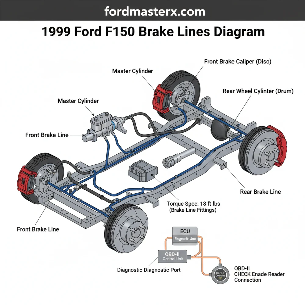
A 1999 Ford F150 brake lines diagram illustrates the routing from the master cylinder and ABS module to each wheel. It identifies the primary front lines, the long rear feed line, and individual flex hoses. Using this map ensures correct installation, proper fluid flow, and helps maintain the correct torque spec for fittings.
📌 Key Takeaways
- Visualizes the hydraulic path from the master cylinder to the wheels
- Identifies the ABS module as the central distribution hub
- Emphasizes using flare nut wrenches to protect metal fittings
- Assists in verifying leak-free connections for safety
- Used primarily for replacing corroded or damaged steel lines
The 1999 Ford F-150 remains a staple of American roads, representing the tenth generation of the “Built Ford Tough” legacy. However, as these vehicles age, one of the most critical maintenance tasks for any DIY enthusiast is addressing the brake hydraulic system. Rust and corrosion frequently attack the steel lines, particularly in “salt belt” states, leading to soft pedals or total brake failure. Understanding the 1999 Ford F-150 brake line diagram is not just about identifying where pipes go; it is about understanding the flow of hydraulic pressure from your foot to the brake pads. This guide provides a comprehensive breakdown of the system layout, fitting sizes, and routing to help you navigate a full line replacement or a simple repair.
Main Components and System Features
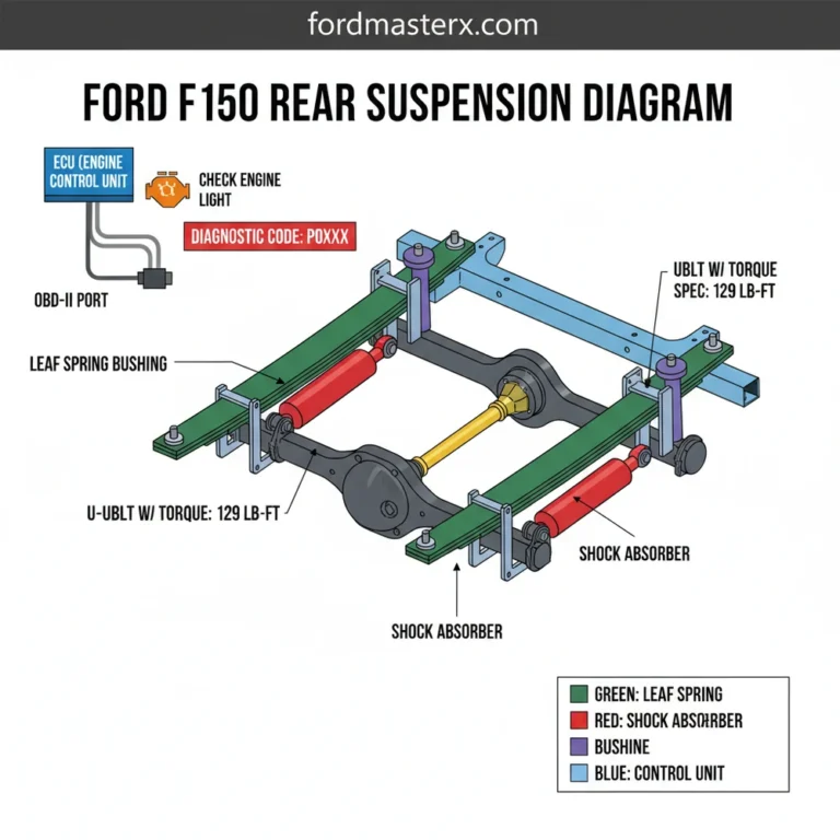
The 1999 F-150 uses a split-diagonal or front-to-rear hydraulic circuit, depending on whether the truck is equipped with Rear-Wheel ABS (RABS) or Four-Wheel ABS (4WABS). Understanding which system you have is the first step in reading the diagram correctly. You can identify your system by looking for the ABS pump; the 4WABS module is a large aluminum block with multiple lines located on the driver’s side inner fender, while the RABS system features a smaller valve located further down the frame rail.
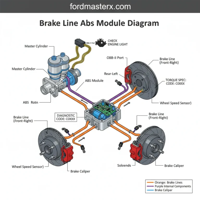
1. Master Cylinder and Reservoir: This is the heart of the system. It features two primary ports. The port closest to the firewall typically feeds the front brakes, while the front port feeds the rear circuit. In the 1999 model, the master cylinder ports usually utilize different thread sizes (such as 1/2-20 and 7/16-24) to prevent cross-connection during assembly.
2. ABS Module/Hydraulic Control Unit (HCU): In 4WABS models, all lines from the master cylinder go directly into the HCU. From there, four separate lines exit: one for each front wheel and one that eventually splits for the rear wheels. For RABS models, the front lines are often split via a “T” fitting or directly at the master cylinder, while the rear line passes through the RABS valve.
3. The Front Brake Lines:
- Driver Side (Left Front): This is the shortest run in the system. It exits the ABS module or distribution block and travels down to a bracket on the frame, where it connects to a flexible rubber hose.
- Passenger Side (Right Front): This line is significantly longer. It must travel from the driver’s side, across the front crossmember (usually tucked behind the steering rack or engine cradle), and over to the passenger side frame rail.
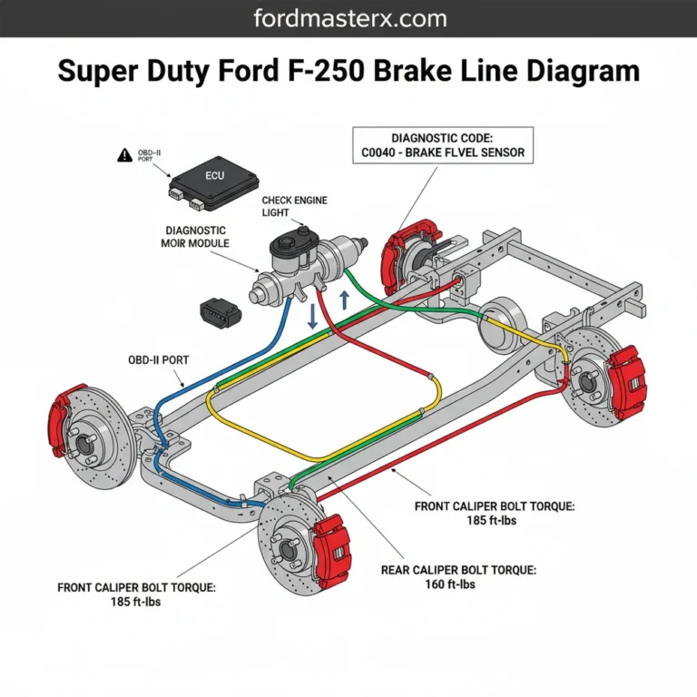
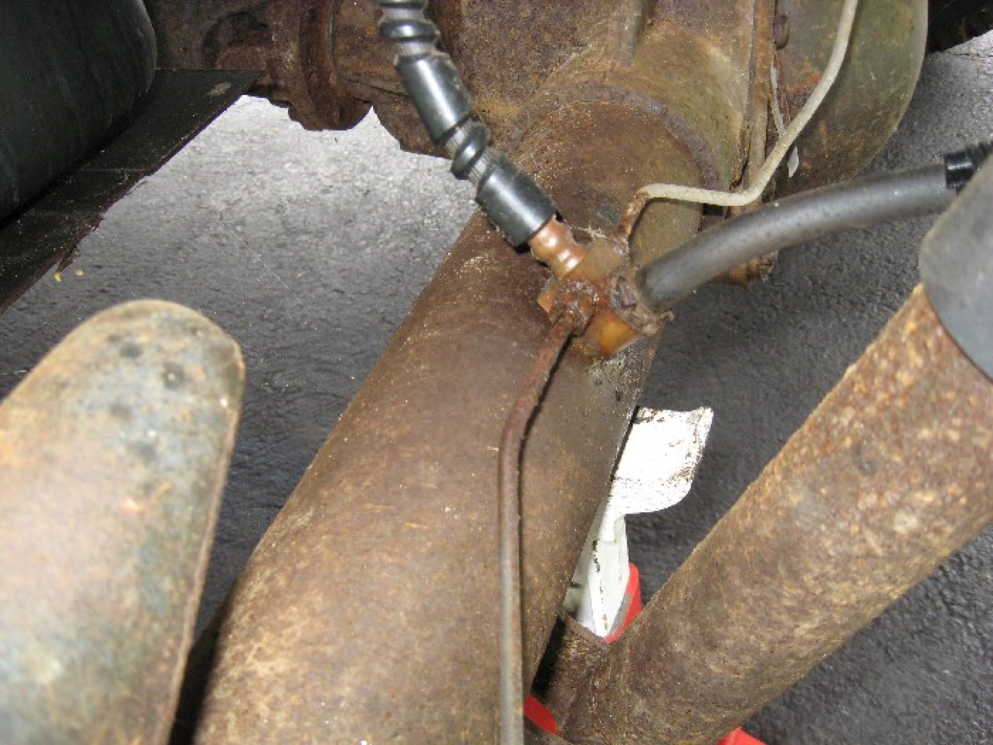
4. The Rear Brake Line (Main Feed): This is the most notorious line for 1999 F-150 owners. It runs from the engine bay, down the driver’s side frame rail, and terminates at a flexible hose above the rear differential. This line is often prone to rotting out where it is clipped to the frame or where it passes behind the fuel tank, making it difficult to access without lowering the tank.
5. Rear Axle Lines: Once the main feed reaches the rear axle, it connects to a “T” fitting on the rear flexible hose. From this junction, two hard lines (often called “axle lines”) run along the top of the axle housing to the wheel cylinders (for drum brakes) or calipers (for disc brakes).
How to Use and Read the Brake Line Diagram

When looking at a physical or mental diagram of the 1999 F-150, you should visualize the system as a tree. The master cylinder is the trunk, the ABS module is the main fork, and the lines are the branches extending to the corners of the vehicle.
Mapping the Ports: If you are looking at the ABS module (4WABS), the ports are often stamped with codes. “MC1” and “MC2” refer to the inputs from the Master Cylinder. “LF” stands for Left Front, “RF” for Right Front, and “RI” or “R” for Rear Inlet/Outlet. Following these stamps is more reliable than a visual diagram because aftermarket modules may have slightly different orientations.
Identifying Fitting Sizes: One of the most frustrating parts of reading the diagram is the variation in nuts. While the tubing is 3/16″, the threaded nuts (fittings) vary to prevent assembly errors:
- Standard Nut: 3/8-24 threads (used at the wheel cylinders and flexible hose junctions).
- Large Master Cylinder Nut: 1/2-20 or 9/16-18 (used at the master cylinder ports).
- Metric Variations: Some 1999 models, especially those built late in the year, may utilize M10x1.0 or M12x1.0 fittings at the ABS module. Always use a thread pitch gauge if you are making your own lines.
Helpful Tips for Brake Line Replacement
If your diagram-reading leads you to the conclusion that you need to replace your lines, follow these field-tested tips to make the job easier on your 1999 F-150.
1. Use NiCopp Tubing: If you are bending your own lines, use Copper-Nickel (NiCopp) instead of standard coated steel. NiCopp is much easier to bend by hand, flares more reliably, and is virtually immune to the rust that destroyed your original lines. It is DOT-approved and perfect for the complex bends required to go around the F-150’s fuel tank.
2. The “Fuel Tank Shortcut”: The factory rear brake line is installed before the fuel tank is placed on the frame. To replace it without removing the tank, you can often “fish” the new line through the plastic clips, or alternatively, route the new line along the top of the frame rail using insulated P-clamps to secure it. Just ensure the line is protected from vibrating against sharp edges.
3. Flare Nut Wrenches are Mandatory: Never use a standard open-ended wrench on brake line fittings. Use a flare nut wrench (also known as a line wrench). These grip the nut on five sides, preventing the rounding of the soft metal fittings that is so common on older Ford trucks.
4. Bench Bleeding: If your diagram shows you have disconnected the lines at the master cylinder, you must bench bleed the master cylinder before reconnecting it. Failing to do this will trap a massive air pocket in the cylinder that is almost impossible to remove through standard bleeding at the wheels.
Troubleshooting Common Issues
Even with a perfect diagram, things can go wrong. Here are the most common troubleshooting scenarios for the 1999 F-150 brake system.
Symptom: Spongy Pedal After Replacement
If you’ve replaced lines and the pedal still feels soft, the most likely culprit is air trapped in the ABS HCU. For the 1999 F-150, you often need a scan tool to perform an “Automated Bleed Procedure.” This cycles the internal valves of the ABS pump to purge air. If you don’t have a scan tool, some enthusiasts carefully drive the truck on a gravel road and engage the ABS by braking hard, then re-bleeding the system manually.
Symptom: One Wheel Not Bleeding
If you are getting fluid to three wheels but one is dry, check the flexible rubber hose at that wheel. Over time, these hoses can collapse internally, acting like a one-way check valve. While the hard line (the metal part) might be clear, the hose is often the bottleneck.
Symptom: Leaks at the Flare
If a new connection is weeping fluid, do not simply overtighten it. Loosen the nut, wiggle the line to ensure it is perfectly centered in the port, and then retighten. If it continues to leak, inspect the flare. A lopsided double-flare is the most common cause of leaks in DIY brake jobs.
Brake Line Routing Locations to Check for Corrosion:
- Under the Driver’s Door: Where the lines transition from the vertical engine bay to the horizontal frame rail.
- Above the Fuel Tank: Moisture and road salt get trapped between the tank and the frame, eating the line.
- Rear Axle Junction: The “T” fitting on the rear axle often collects mud and debris, leading to localized pitting.
By understanding the layout and technical specifications of the 1999 Ford F-150 brake system, you can ensure your truck remains safe for the road. Whether you are performing a localized patch or a complete “frame-back” line replacement, staying methodical and using the right materials will make the difference between a successful repair and a dangerous failure.
Step-by-Step Guide to Understanding the Ford F150 Brake Lines Diagram: Easy Routing Guide
Identify the brake line layout using the master cylinder as your starting point for routing.
Locate the ABS module and individual line ports to determine which line serves each wheel.
Understand how the lines are secured along the frame rail with plastic clips and brackets.
Apply the correct torque spec when threading new fittings into the calipers or ABS block.
Verify that there are no leaks and the brake pedal feels firm after bleeding the system.
Complete the process by clearing any diagnostic code from the ECU using an OBD-II scanner.
Frequently Asked Questions
Where is the ABS module located?
The ABS module on this truck is typically located on the driver-side inner fender well, just below the master cylinder. It acts as the central hub where the ECU processes braking pressure. Following the 1999 Ford F150 brake lines diagram will show lines entering and exiting this unit for each wheel.
What does the brake line diagram show?
This diagram provides a visual map of the entire hydraulic system, including the master cylinder, ABS control unit, and the routing of steel lines along the frame rail. It is essential for identifying which line leads to which wheel, especially when the check engine light or brake warning light triggers.
How many connections does the master cylinder have?
The master cylinder features two primary ports that connect to the ABS module or proportioning valve. From there, the system splits into four distinct paths for each wheel. Each connection must be tightened to the specific torque spec to ensure a pressurized, leak-free environment that prevents air from entering the system.
What are the symptoms of a bad brake line?
Symptoms include a spongy brake pedal, visible fluid leaks under the chassis, or a sudden loss of braking power. If a leak causes pressure drops, the OBD-II system might store a diagnostic code related to the ABS sensor. Regularly inspect the lines for heavy corrosion or wet spots along the frame.
Can I replace these brake lines myself?
Yes, you can replace brake lines yourself if you have the proper flaring tools and flare nut wrenches. However, it is a safety-critical task. You must be able to bleed the entire system afterwards to remove air, ensuring the ECU doesn’t detect a pressure imbalance that could trigger a warning.
What tools do I need for brake line replacement?
You will need a set of flare nut wrenches, a tube cutter, a double-flaring tool kit, and fresh DOT 3 brake fluid. If you are diagnosing an electrical fault alongside a hydraulic leak, an OBD-II scanner can help read any stored diagnostic code that appeared when the brake system failed.