Ford F150 4.6 Spark Plug Wire Diagram: Easy Setup Guide
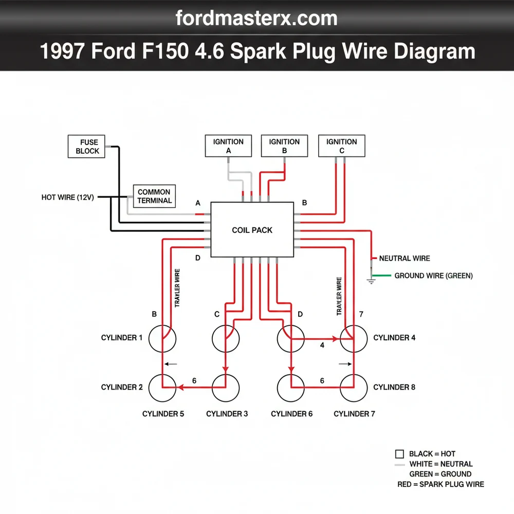
The 1997 Ford F150 4.6L V8 utilizes two coil packs with a firing order of 1-3-7-2-6-5-4-8. Each wire acts as a traveler wire from the coil pack to the spark plug. Ensure the common terminal on each coil is connected to the correct cylinder to maintain engine timing and performance.
📌 Key Takeaways
- The 4.6L engine uses two separate coil packs located at the front of the engine.
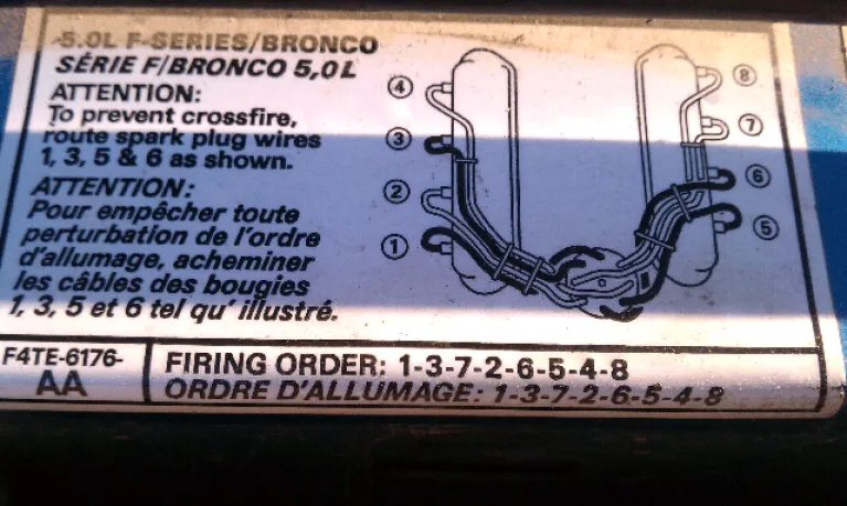
- The correct firing order (1-3-7-2-6-5-4-8) is critical for engine operation.
- Engine blocks serve as the ground wire to complete the high-voltage circuit.
- Always replace wires one at a time to prevent routing errors.
- Use this diagram whenever replacing plugs, wires, or diagnosing ignition misfires.
Restoring the performance of a legendary workhorse like the 1997 Ford F150 requires attention to detail, especially when dealing with the ignition system. If you have ever experienced a sudden engine hesitation, a rough idle, or a drop in fuel economy, the culprit is often a misplaced or failing ignition lead. Finding a reliable 1997 ford f150 4.6 spark plug wire diagram is the first step in ensuring your 4.6L V8 Modular engine runs with the precision it was designed for. In this guide, we will break down the complexities of the Ford waste-spark system, providing you with a clear roadmap for wire routing, cylinder identification, and coil pack connections. By the end of this article, you will have the technical knowledge to perform a professional-grade tune-up, ensuring every volt reaches its intended destination.
The ignition system on the 1997 Ford F150 4.6L engine is unique because it utilizes a dual coil pack configuration rather than a single distributor or individual coil-on-plug units. This setup consists of two separate coil blocks, each responsible for firing four cylinders. To read the diagram correctly, you must first understand the cylinder numbering convention used by Ford. When standing at the front of the truck looking at the engine, the cylinders on the passenger side are numbered 1, 2, 3, and 4 (from front to back). The cylinders on the driver’s side are numbered 5, 6, 7, and 8 (also from front to back).
The diagram itself is a visual mapping of how these eight cylinders connect to the two coil packs mounted at the front of the engine. Unlike a simple residential circuit where you might find a traveler wire or a neutral wire tied to a brass screw, this automotive system uses high-voltage secondary ignition wires to deliver a spark. The coil packs are divided into specific towers. Each tower is a common terminal for a specific spark plug wire. The diagram illustrates that the system operates on a “waste spark” principle, meaning one coil fires two cylinders simultaneously—one on the compression stroke and one on the exhaust stroke. This requires a specific gauge of wire, typically 7mm or 8mm, to handle the massive electrical load without leaking voltage to the engine block, which acts as the ground wire for the entire circuit.
| COIL PACK LOCATION | TOWER POSITION | CONNECTS TO CYLINDER |
|---|---|---|
| PASSENGER SIDE COIL | Top Left / Top Right | 1 / 6 |
| PASSENGER SIDE COIL | Bottom Left / Bottom Right | 3 / 5 |
| DRIVER SIDE COIL | Top Left / Top Right | 4 / 7 |
| DRIVER SIDE COIL | Bottom Left / Bottom Right | 2 / 8 |
Note: Left/Right is determined while facing the front of the coil pack towers.
The firing order for the 1997 Ford F150 4.6L V8 is 1-3-7-2-6-5-4-8. Proper wire routing according to the diagram is essential to prevent Induction Crossfire, which can cause engine knock and internal damage.
Performing a spark plug wire replacement using the 1997 ford f150 4.6 spark plug wire diagram is a straightforward process if you follow a logical sequence. Before beginning, ensure the engine is cool to the touch to avoid burns and to prevent the spark plug threads from seizing in the aluminum cylinder heads.
Step 1: Gather Your Tools and Materials
You will need a set of high-quality ignition wires (8mm gauge is recommended for better insulation), a spark plug wire puller tool, dielectric grease, and a 7mm socket if you need to remove the coil pack brackets. While you aren’t working with a hot wire in the sense of a live household 110V circuit, the ignition system can hold a residual charge, so disconnecting the negative battery terminal is a recommended safety precaution.
Step 2: Identify Cylinder Locations
Stand at the front bumper. The bank on your left (Passenger side) contains cylinders 1-2-3-4. The bank on your right (Driver side) contains cylinders 5-6-7-8. It is helpful to use a masking tape and a marker to label each wire before removal.
Step 3: Map the Passenger Side Coil Pack
The passenger side coil pack is located near the front of the engine on the passenger bank. According to the wiring diagram, the towers are mapped as follows:
- ✓ Top Front Tower: Cylinder 1
- ✓ Top Rear Tower: Cylinder 6
- ✓ Bottom Front Tower: Cylinder 3
- ✓ Bottom Rear Tower: Cylinder 5
Step 4: Map the Driver Side Coil Pack
Move to the driver side coil pack. This one follows a different sequence:
- ✓ Top Front Tower: Cylinder 4
- ✓ Top Rear Tower: Cylinder 7
- ✓ Bottom Front Tower: Cylinder 2
- ✓ Bottom Rear Tower: Cylinder 8
Step 5: One-by-One Replacement
To avoid confusion, replace one wire at a time. Remove the old wire from the spark plug and the coil tower. Match the length of the old wire with a new one from your kit. Apply a small amount of dielectric grease inside the boots at both ends. This prevents moisture intrusion and ensures the boot doesn’t fuse to the porcelain of the spark plug or the plastic of the coil tower.
Step 6: Routing and Looming
This is the most critical part of the installation. Route the wires through the factory plastic looms and clips. Ensure the wires do not touch the exhaust manifolds or sharp metal edges. Proper spacing is necessary to prevent “induction” where voltage from one wire jumps to an adjacent wire, causing a premature spark in the wrong cylinder.
Step 7: Final Connection and Testing
Press the boots firmly onto the spark plugs and coil towers until you hear or feel a “click.” This indicates the metal terminal has fully seated. Reconnect your battery and start the engine. Listen for a smooth idle and watch for any “Check Engine” lights on the dashboard.
Never pull on the wire itself when removing it from a spark plug. Always grasp the boot. Pulling the wire can break the internal carbon core, leading to high resistance and misfires that are difficult to diagnose.
Even with a perfect diagram, issues can arise during or after installation. The most frequent problem users encounter is a “crossed wire” situation where cylinders 5 and 6 or 4 and 7 are swapped. This results in a violent engine shake and popping sounds from the intake or exhaust. The 1997 ford f150 4.6 spark plug wire diagram helps solve this by providing a visual double-check of the coil tower positions.
Another common issue is “arc-over.” If you see blue sparks jumping from the wires to the engine block at night, your wires have failed insulation. Unlike a household neutral wire which carries current back to the source safely, a leaking ignition wire will seek the nearest ground wire or metal surface, stealing energy from the spark plug. If you experience a P0301 through P0308 diagnostic trouble code, refer back to the diagram to ensure the specific cylinder identified by the code is connected to the correct coil tower. If the wiring is correct and the misfire persists, the coil pack itself may have an internal crack.
When installing wires, use a “criss-cross” routing pattern if two wires must run parallel for a long distance. Running wires parallel for long stretches can cause electromagnetic interference. Crossing them at a 90-degree angle minimizes this risk.
To maintain the integrity of your ignition system, quality is paramount. When purchasing parts, opt for wires with a thick silicone jacket and high-temp boots. Cheap wires often use a lower gauge and inferior insulation that degrades under the extreme heat of the F150’s engine bay.
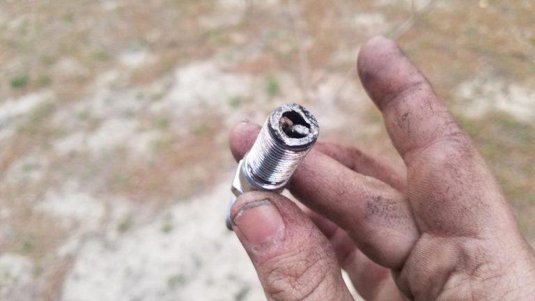
For the best results, always inspect your spark plugs while the wires are off. Look for a light tan color on the porcelain; if they are blackened or oily, the issue may be deeper than just the wiring. Maintenance recommendations for the 1997 F150 suggest replacing the ignition wires every 60,000 to 100,000 miles, depending on driving conditions. Cost-saving advice includes buying a complete “tune-up kit” which often bundles wires, plugs, and filters at a lower price than buying them individually. Finally, ensure the common terminal on the coil pack is clean and free of corrosion. If you see green oxidation, use a small wire brush to clean the terminal before snapping the new wire into place. This ensures maximum voltage delivery and a long-lasting repair.
By strictly adhering to the 1997 ford f150 4.6 spark plug wire diagram and following these professional best practices, you can restore your truck’s power and reliability. Whether you are navigating heavy traffic or hauling a trailer, a properly wired ignition system is the foundation of a dependable Ford F150.
Step-by-Step Guide to Understanding the Ford F150 4.6 Spark Plug Wire Diagram: Easy Setup Guide
Identify the cylinders – Label each cylinder 1-4 on the passenger side and 5-8 on the driver side.
Locate the coil packs – Find the two ignition coils mounted at the front of the engine manifold.
Understand how each traveler wire flows – Trace the wire from the coil pack tower to its corresponding spark plug.
Connect the hot wire leads – Firmly press the new wire boots onto the spark plugs and coil terminals until they click.
Verify that the ground wire path is clear – Ensure the spark plug threads are clean for a solid connection to the engine block.
Complete the installation – Check all wire routing to ensure they are away from hot exhaust manifolds and moving parts.
Frequently Asked Questions
Where is the spark plug wire located?
On the 1997 Ford F150 4.6L, the spark plug wires are located on top of the engine. They run from the two ignition coil packs mounted on the front of the intake manifold to the spark plugs recessed inside the cylinder heads on both the left and right banks.
What does this wiring diagram show?
This diagram displays the exact path each spark plug wire takes from the coil pack to the specific cylinder. It acts as a guide for the firing order, showing which hot wire connection triggers which cylinder, ensuring the engine cycles correctly without hesitation or backfiring during the combustion process.
How many wires and connections does the 4.6 engine have?
The 4.6L V8 engine has eight spark plug wires and two coil packs. Each coil pack has four towers. Unlike home electrical systems that require a neutral wire, this DC system uses the spark plug’s threaded connection to the cylinder head as the primary return path for the ignition spark.
What are the symptoms of a bad spark plug wire?
Common symptoms include engine misfiring, a rough idle, or a significant drop in fuel economy. You may also notice the ‘Check Engine’ light flashing under load. Physically, bad wires may show cracks, burns, or white ‘arc’ marks where electricity is leaking through to a nearby metal surface.
Can I replace these spark plug wires myself?
Replacing spark plug wires is a manageable DIY task for most owners. It requires no heavy machinery, only basic hand tools. By following the diagram to ensure each traveler wire reaches its designated cylinder, you can complete the job in about an hour and save on professional labor costs.
What tools do I need for this task?
To perform a wire replacement, you will need a spark plug wire puller, a 5/8-inch spark plug socket, and a ratchet with an extension. Additionally, applying dielectric grease to the common terminal inside the boot is recommended to prevent moisture intrusion and make future removals much easier.