Ford Expedition Radio Wiring Diagram: Easy Setup Guide
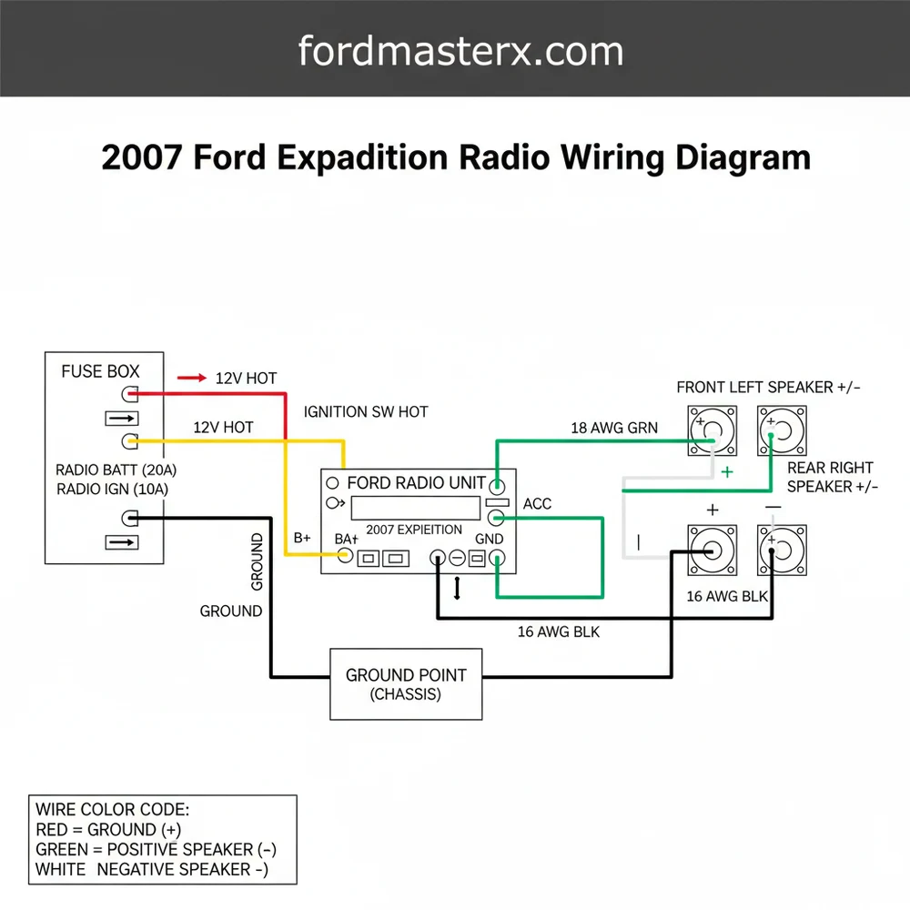
The 2007 Ford Expedition radio wiring diagram illustrates how the factory harness connects to the head unit. It identifies the constant 12V hot wire, the ignition-switched wire, and the ground wire for power. Additionally, it maps out speaker outputs and the neutral wire configurations to ensure proper audio clarity across all channels.
📌 Key Takeaways
- Provides exact color codes for factory audio integration
- Essential for identifying power, ground, and speaker leads
- Always disconnect the battery before tampering with wiring
- Use a harness adapter to avoid cutting factory wires
- Useful for aftermarket head unit or amplifier installations
Replacing the factory head unit in a full-size SUV requires precision, especially when navigating the complex electrical architecture of a 2007 Ford Expedition. Whether you are upgrading to a modern touchscreen with Apple CarPlay or simply repairing a faulty factory unit, having a reliable 2007 ford expedition radio wiring diagram is the foundation of a successful project. This guide provides a detailed breakdown of the wire colors, pin locations, and terminal functions within the dashboard. By understanding these connections, you can ensure that your new audio system functions perfectly without damaging the vehicle’s sensitive electronic control modules or draining the battery.
The 2007 Ford Expedition uses a CAN-bus system for many of its radio functions. This means a standard “switched” 12V accessory wire may not be present in the factory harness, as the radio is often turned on by a data signal rather than a direct current. Understanding how to bridge this with a digital interface is critical for DIY installers.
Decoding the 2007 Ford Expedition Radio Wiring Diagram
The 2007 Ford Expedition typically features two or three distinct harnesses depending on the trim level (XLT, Eddie Bauer, or Limited) and whether the vehicle is equipped with the Audiophile or THX premium sound system. The main harness is a 24-pin connector that handles the primary power, ground, and speaker outputs.
In standard electrical applications, you might look for a common terminal or a brass screw to identify a return path, but in the automotive world, we rely on color-coded insulation and pin positions. The ground wire in this vehicle is typically Black with a Light Green stripe. This serves as the return path to the chassis, much like a neutral wire functions in a residential AC circuit to complete the loop.
The hot wire—or the constant 12V power source—is usually Light Green with a Violet stripe. This wire maintains the radio’s memory (clock settings and station presets) even when the ignition is off. It is vital to use the correct gauge of wire when extending these connections to prevent voltage drops that can lead to distorted audio or “brown-outs” of the head unit display.
For those with the premium Audiophile system, a secondary harness manages the center channel speaker and the powered subwoofer located in the rear cargo area. Unlike a simple traveler wire in a three-way lighting circuit that toggles power, the remote turn-on wire in this system sends a low-amp 5V to 12V signal to the factory amplifier to wake it up. If this connection is missed, your new radio will turn on, but no sound will come from the speakers.
Step-by-Step Installation and Interpretation Guide

Interpreting a wiring diagram and translating it into a physical installation requires a methodical approach. Follow these steps to ensure a professional-grade result.
- ✓ Step 1: Battery Disconnection. Always disconnect the negative battery terminal before touching any internal wiring. This prevents accidental shorts that could blow the main fuse or damage the vehicle’s Body Control Module (BCM).
- ✓ Step 2: Dash Disassembly. Use plastic pry tools to remove the trim bezel surrounding the radio. Remove the four 7mm screws holding the factory unit in place and gently pull the unit forward to expose the rear connectors.
- ✓ Step 3: Map the Harnesses. Compare your aftermarket wiring harness adapter to the 2007 ford expedition radio wiring diagram. Match the colors from the adapter to the new radio’s harness. Note that the adapter usually follows the EIA standard (Yellow for constant, Red for switched), while the Ford factory wires use the colors mentioned in the diagram section.
- ✓ Step 4: Establish the Power and Ground. Connect the hot wire (Constant 12V) and the ground wire. If your vehicle lacks a switched accessory wire in the harness due to CAN-bus, you may need to run a separate “traveler” lead to the fuse box or use a CAN-bus interface module to
- ✓ Step 5: Wire the Speakers. Follow the polarity carefully. Connecting a positive (+) output to a negative (-) terminal will put the speakers “out of phase,” resulting in thin, tinny sound and a total lack of bass response.
- ✓ Step 6: Secure Connections. Use solder and heat shrink or high-quality crimp connectors. Avoid “twisting and taping,” as the vibrations of a moving vehicle will eventually loosen these points, causing intermittent power loss.
- ✓ Step 7: Testing. Before re-assembling the dash, reconnect the battery and test all functions: FM/AM reception, Bluetooth, and all four corner speakers. Ensure the subwoofer is engaging if applicable.
Do not use a test light on the factory wiring in this vehicle. The 2007 Expedition uses data lines that operate on low voltage; a standard test light can draw too much current and fry delicate circuits. Always use a high-impedance digital multimeter to check for voltage.
Tools and Materials Needed
To complete this job, gather the following:
– Digital Multimeter (for verifying 12V voltage)
– 7mm and 10mm sockets
– Wire strippers and crimpers
– Plastic trim removal kit
– Heat shrink tubing
– Soldering iron (optional but recommended)
– Vehicle-specific wiring harness adapter
Common Issues & Troubleshooting

Even with a perfect diagram, obstacles can arise during a 2007 Ford Expedition radio installation. One frequent issue is the “no sound” condition. This is almost always caused by the failure to power the factory amplifier. In the Audiophile system, the Dark Blue/White wire must receive a 12V trigger from the aftermarket radio’s “Remote Turn-on” output. If your radio provides 12V but the factory amp expects 5V, you may hear a loud “pop” when the radio turns on; this requires a 5V regulator or a 1.5k ohm resistor to correct.
Another common problem is the loss of memory. If your radio resets every time you turn off the engine, the hot wire (Constant) and the Switched wire are likely swapped. The constant wire must be connected to the terminal that always shows 12V on your multimeter, regardless of the key position.
Finally, “alternator whine” or buzzing in the speakers often points to a poor ground. Ensure your ground wire is connected to a clean, unpainted metal surface or the common terminal ground pin in the factory harness. If the factory ground is insufficient, you can create a new ground by securing a ring terminal to a structural brass screw or bolt behind the dash.
Tips & Best Practices for Audio Excellence
When working with the 2007 Ford Expedition’s electrical system, quality should be your priority. Because this vehicle is a larger SUV, the wire runs are long, and the environment can get hot. Always choose a wire gauge that meets or exceeds the factory specifications to ensure consistent power delivery.
If you are retaining the factory steering wheel controls, you will need a separate interface module. Map the “Data” wires from the 2007 ford expedition radio wiring diagram to the interface’s input. This allows the digital signals from your steering wheel to be translated into commands the new radio understands.
Maintenance and Long-Term Reliability
– Avoid Electrical Tape: Over time, the adhesive on electrical tape breaks down in the heat, leaving a sticky mess and exposed wires. Use heat-shrink tubing for a permanent, weather-resistant seal.
– Strain Relief: Bundle your wires with zip ties so the weight of the harness isn’t pulling on the connectors when the radio is pushed back into the cavity.
– Bypass Modules: Consider using a premium harness interface (like those from PAC or Metra). These modules handle the CAN-bus data for you, providing a pre-wired “switched” power lead, illumination wire, and even a parking brake trigger for video units.
Investing the time to study the 2007 ford expedition radio wiring diagram before you start cutting wires will save hours of frustration. By respecting the vehicle’s electrical architecture and using the right tools to verify voltage and ground integrity, you can enjoy a high-fidelity audio experience that feels like it came straight from the factory. Whether you’re chasing a faulty neutral wire equivalent in a ground loop or simply seeking the right hot wire for your memory lead, this guide serves as your roadmap to a successful upgrade.
Frequently Asked Questions
Where is the radio fuse located?
The radio fuse for the 2007 Ford Expedition is typically found in the passenger-side kick panel fuse box. Look for fuse #7 (5A) or fuse #39 (20A) depending on your specific audio trim level. Consult the diagram to verify the circuit path from the hot wire to the head unit.
What does this wiring diagram show?
This diagram provides a visual map of the electrical connections for the audio system. It details the traveler wire paths for steering wheel controls, the common terminal points for grounding, and the color-coded paths for every speaker in the vehicle’s multi-speaker setup, ensuring a seamless aftermarket installation process.
How many wires does the radio harness have?
The main harness usually contains 14 to 24 wires depending on whether you have the base audio or the Audiophile system. It includes the ground wire, illumination leads, and signal wires. Some setups use a common terminal for shared grounds in specific amplifier configurations found in the center console.
What are the symptoms of a bad radio connection?
Symptoms include no power, speakers cutting out, or static noise. If the hot wire is loose, the radio will reset frequently. A faulty ground wire often causes a whining sound that changes with engine RPM, indicating poor electrical isolation within the vehicle’s power distribution system or internal head unit.
Can I install a new radio myself?
Yes, with this wiring diagram, installing a new radio is a manageable DIY task. By matching the aftermarket harness to the factory colors—identifying the neutral wire and power leads—you can avoid expensive professional installation fees while ensuring all features, like subwoofers or auxiliary inputs, function correctly and safely.
What tools do I need for this task?
You will need a set of trim removal tools to avoid cracking the dashboard, a 7mm socket for the mounting bolts, and wire strippers. For a secure connection, use a soldering iron or crimp connectors to join the traveler wire and power leads to your new stereo’s wiring harness.