Ford Escape Engine Diagram: Diagnosis & Fix Guide
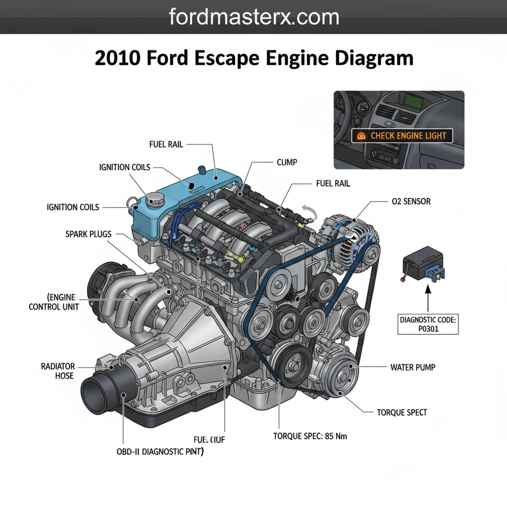
The 2010 Ford Escape engine diagram provides a visual layout of the 2.5L I4 and 3.0L V6 powerplants. It highlights critical components such as the intake manifold, throttle body, and sensor locations. This map is essential for tracing vacuum lines, identifying electrical connectors, and locating mechanical parts during routine maintenance.
📌 Key Takeaways
- Provides visual identification for complex engine bay components
- The ECU is the most critical component to identify for electronic control
- Always disconnect the battery before working near electrical engine sensors
- Reference a specific torque spec for every bolt to prevent engine leaks
- Use this diagram when troubleshooting a check engine light or diagnostic code
Understanding the mechanical layout of your vehicle is the first step toward successful DIY maintenance and reliable repairs. This guide provides a comprehensive look at the 2010 Ford Escape engine diagram, specifically designed to help owners and enthusiasts navigate the complexities of both the 2.5L I4 and the 3.0L V6 powerplants. By identifying key components such as sensors, belts, and fluid pathways, you can effectively troubleshoot performance issues and extend the lifespan of your vehicle. In this article, you will learn how to read technical schematics, identify critical engine parts, and apply this knowledge to solve common mechanical problems using professional-grade diagnostic techniques.
The 2010 Ford Escape was manufactured with two primary engine options: the 2.5L Duratec 25 I4 and the 3.0L Duratec 30 V6. While their layouts differ, they share similar logic regarding sensor placement and cooling system architecture.
Decoding the 2010 Ford Escape Engine Diagram
A 2010 Ford Escape engine diagram serves as a blueprint for the vehicle’s propulsion system. At first glance, the diagram captures the top-down perspective of the engine bay, highlighting the orientation of the engine block relative to the firewall and the radiator support. The diagram distinguishes between the electrical system, the fuel delivery system, and the mechanical drive components. For the 2.5L inline-four engine, the layout is relatively linear, with the intake manifold situated at the front of the bay, while the 3.0L V6 features a transverse mounting where the rear cylinder bank sits closer to the cabin.
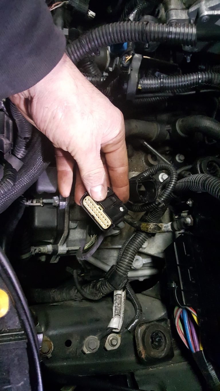
Key elements in the diagram include the accessory belt (serpentine belt) routing, which is vital for the operation of the alternator, air conditioning compressor, and water pump. The diagram also illustrates the positioning of the ECU (Electronic Control Unit), which acts as the brain of the vehicle, processing data from various sensors. You will also find the locations for the ignition coils, spark plugs, and the throttle body. Visual indicators in high-quality diagrams often use solid lines for physical connections and dashed lines for electrical harnesses or vacuum hoses.
Color-coding is frequently employed in these diagrams to simplify identification. Red often signifies high-voltage electrical paths or heat-intensive areas, while blue is reserved for the cooling system and coolant flow. Understanding these visual cues allows you to quickly locate a specific component, such as the MAF (Mass Air Flow) sensor or the EGR (Exhaust Gas Recirculation) valve, without having to dismantle unrelated parts of the engine.
[DIAGRAM_PLACEHOLDER: 2010 Ford Escape Engine Layout – 2.5L and 3.0L Top-Down View showing Accessory Belt, ECU location, and Intake Manifold]
Step-by-Step Guide to Reading and Applying the Diagram

Interpreting an engine diagram requires a systematic approach to ensure you are looking at the correct orientation and component. Whether you are performing a simple belt change or investigating a complex electrical fault, follow these steps to use the diagram effectively.
1. Orient the Diagram to the Vehicle
Before you begin, stand at the front bumper of your Escape. The diagram is usually drawn from this perspective. Identify the “front” of the engine, which is the side with the accessory belt, regardless of whether the engine is mounted transversely. Locate the battery and the air box to provide a physical anchor for the drawing.
2. Identify the Accessory Belt Path
Locate the accessory belt routing on the diagram. This is a continuous loop that connects several pulleys. It is crucial to note which side of the belt (ribbed or smooth) touches each pulley. If you are replacing the belt, draw a quick sketch based on the diagram before removing the old one to ensure the tensioner is applied correctly during reassembly.
Never attempt to service the accessory belt or cooling system while the engine is hot. Pressurized coolant can cause severe burns, and moving belts can cause finger injuries.
3. Locate Diagnostic Sensors for OBD-II Analysis
When a check engine light appears, use the diagram to find the sensors associated with the diagnostic code you received. For example, if you have an oxygen sensor code, the diagram will show the locations of Sensor 1 (upstream) and Sensor 2 (downstream) on the exhaust manifold and catalytic converter. This prevents you from replacing the wrong part.
4. Trace the Coolant Flow
Follow the paths labeled for coolant flow. Start at the radiator, follow the upper hose to the thermostat housing, and trace the internal passages through the engine block back to the water pump. This is essential for diagnosing overheating issues or air pockets within the system after a fluid flush.
5. Reference Torque Spec Requirements
Modern engines like those in the 2010 Escape use many aluminum components. Use the diagram to identify specific bolts, such as those on the valve cover or intake manifold, and look up the corresponding torque spec. Over-tightening can crack the manifold, while under-tightening leads to vacuum leaks.
6. Inspect the Timing Chain Cover
While the diagram shows the timing chain internally, it will point you to the front cover where oil leaks often occur. Unlike older engines with rubber belts, the 2010 Escape uses a timing chain designed to last the life of the vehicle, but the tensioners and guides may eventually require inspection through the access points noted in the schematic.
- ✓ 10mm and 12mm sockets (standard for Ford engine components)
- ✓ Torque wrench (calibrated in inch-pounds and foot-pounds)
- ✓ OBD-II scanner for reading system data
- ✓ Multimeter for testing sensor voltage
Common Issues and Troubleshooting

The 2010 Ford Escape is a robust vehicle, but it does have frequent issues that an engine diagram can help resolve. One of the most common complaints is the illumination of the check engine light due to vacuum leaks or sensor failure. By using the diagram to trace vacuum lines, you can identify brittle or cracked hoses that cause rough idling.
Another common issue involves the ECU. If the vehicle experiences intermittent stalling or “limp mode,” the diagram helps you locate the ECU and its primary ground wires. Often, a simple cleaning of the ground contact point, as identified in the wiring schematic, can resolve complex electronic glitches. Furthermore, if you encounter a specific diagnostic code like P0300 (Random Misfire), the diagram will show you the exact sequence of the ignition coils, allowing you to swap coils between cylinders to see if the misfire follows the part.
If you are troubleshooting a cooling issue, check the “Coolant Degas Bottle” cap. These are known to fail on the 2010 Escape, preventing the system from holding pressure even if the diagram shows the rest of the flow is clear.
Tips and Best Practices for Engine Maintenance
To keep your 2010 Ford Escape running efficiently, consistency is key. Always use high-quality synthetic oil as recommended by the manufacturer. When referencing your 2010 ford escape engine diagram during an oil change, take a moment to inspect the surrounding components. Look for signs of “weeping” around the timing chain cover or the oil pan gasket.
Maintenance of the accessory belt is often overlooked. You should inspect the belt for glazing or cracking every 30,000 miles. Because the belt drives the alternator, a failure here will leave you stranded with a dead battery. Additionally, ensure your coolant flow remains unobstructed by flushing the system every five years or 100,000 miles. Use only the specific coolant type (usually Motorcraft Orange or equivalent) to prevent internal corrosion of the heater core and radiator.
Finally, keep your ECU connectors clean. If you ever perform an engine bay cleaning, avoid spraying high-pressure water directly onto the ECU or fuse box. Moisture in these areas can lead to a “ghost” diagnostic code that is difficult and expensive to track down. By combining the visual guidance of an engine diagram with these proactive maintenance habits, you can ensure your Ford Escape remains a reliable daily driver for years to come. Investing in a set of high-quality gaskets and sensors when repairs are needed will save you money in the long run by preventing repeat failures and keeping your fuel economy at peak levels.
In conclusion, the 2010 ford escape engine diagram is an indispensable tool for any owner. Whether you are identifying a mysterious noise near the timing chain or trying to understand why a check engine light has appeared, the diagram provides the clarity needed to proceed with confidence. By following the steps and tips outlined in this guide, you can tackle most automotive challenges with the precision of a professional technician.
Frequently Asked Questions
Where is the ECU located?
The ECU on a 2010 Ford Escape is typically found in the engine compartment, mounted on the firewall or near the strut tower. It serves as the brain of the vehicle, managing fuel injection and ignition timing. Locating it is essential for diagnosing complex electrical issues or sensor failures.
What does the engine diagram show?
This diagram shows the physical arrangement of engine components, including the serpentine belt routing, spark plug placement, and sensor locations. It helps users visualize how different systems, like the cooling and intake systems, interact within the engine bay to facilitate easier repairs and parts replacement.
How many connections does the OBD-II port have?
The OBD-II port features a standard 16-pin connector located under the driver-side dashboard. While not directly on the engine, it provides the communication link to the ECU. Using a scanner allows you to pull a diagnostic code when the check engine light illuminates on your dashboard.
What are the symptoms of a bad ignition coil?
A bad ignition coil often triggers a check engine light and causes engine misfires, rough idling, or reduced fuel economy. You may retrieve a specific diagnostic code like P0301 through the OBD-II system. Referencing the engine diagram helps you locate the specific cylinder needing repair.
Can I replace the spark plugs myself?
Yes, replacing spark plugs on the 2.5L model is a straightforward DIY task, though the 3.0L V6 requires removing the intake manifold. Always use the engine diagram to locate each coil-on-plug unit and ensure you follow the manufacturer’s recommended torque spec for the new plugs.
What tools do I need for engine diagnostics?
To diagnose engine issues, you need a basic socket set, a torque wrench to meet every torque spec, and an OBD-II scanner. These tools allow you to read codes, perform mechanical repairs, and verify that all components are properly secured according to the technical engine diagram.