Ford Diesel Tractor Ignition Switch Wiring Diagram Guide
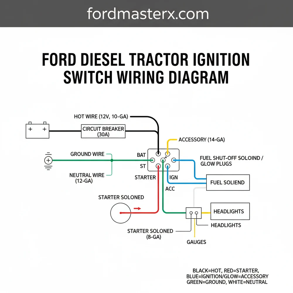
A Ford diesel tractor ignition switch wiring diagram illustrates how the battery hot wire connects to the common terminal. It guides the distribution of power to the starter, glow plugs, and gauges. Ensuring a solid ground wire connection is vital for safety and reliable operation across all switch positions.
📌 Key Takeaways
- Correct terminal mapping prevents starter solenoid damage
- Identifying the common terminal is the first step in wiring
- Always disconnect the battery before working on the ignition
- The neutral safety switch is a critical part of the circuit
- Use a multimeter to verify continuity before final assembly
Restoring or maintaining a vintage machine requires precision, especially when dealing with the complex electrical system of a heavy-duty engine. Locating a reliable and accurate ford diesel tractor ignition switch wiring diagram is the first crucial step toward ensuring your machine starts reliably every time you turn the key. This guide provides a detailed breakdown of the terminal connections, wire colors, and safety protocols necessary for a successful installation or repair. By understanding the flow of current from the battery to the starter and glow plugs, you will learn how to troubleshoot existing issues and prevent future electrical failures in your tractor.
Understanding the Ignition Switch Components
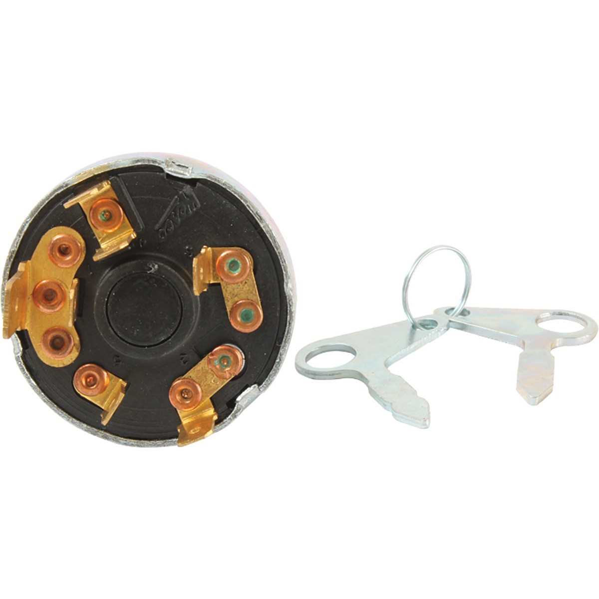
The ignition switch on a Ford diesel tractor serves as the central hub for the machine’s electrical distribution. Unlike a standard gasoline engine, a diesel ignition system must manage the high-current draw of glow plugs or a manifold heater before the starter is engaged. When you look at the back of a standard replacement switch, you will typically find four to five terminals, often secured with a brass screw to ensure a low-resistance connection. These terminals are usually labeled with letters such as B, S, G, and ACC.
The “B” terminal is the common terminal for the incoming power supply. This is where the heavy-gauge hot wire from the battery or the starter solenoid connects to provide constant voltage to the switch. The “S” terminal is responsible for the starter circuit; when the key is turned to the start position, power flows from the common terminal to the starter solenoid via the traveler wire. The “G” or “H” terminal is specific to diesel models, controlling the glow plugs or the intake heater. This circuit is vital for cold-weather starting, as it pre-heats the combustion chamber.
In many Ford configurations, the switch also manages the accessory circuit (ACC), which powers lights, gauges, and the fuel shut-off solenoid. The wiring diagram illustrates how these internal connections bridge when the key is rotated through its various positions: Off, Accessory, Heat, and Start. Understanding this internal logic is essential because a failure in one internal contact can lead to a tractor that turns over but won’t fire, or one that heats the glow plugs but won’t engage the starter.
Most Ford diesel tractors utilize a “ground-isolated” switch body, meaning the ground wire is not typically attached to the switch itself but rather to the components it powers. The switch acts strictly as a gatekeeper for the positive voltage.
[DIAGRAM_PLACEHOLDER: A detailed schematic showing a circular ignition switch back-plate. Terminal B (Center) connected to a Red 10-gauge wire. Terminal S connected to a Brown/White traveler wire leading to the Neutral Safety Switch. Terminal G connected to a Thick Yellow wire leading to Glow Plugs. Terminal ACC connected to a Black/Green wire for the instrument cluster. A Ground wire icon is shown attached to the tractor chassis.]
Step-by-Step Wiring Installation Guide
Properly installing or rewiring your ignition switch requires a methodical approach to ensure safety and functionality. Before beginning, ensure you have a high-quality multimeter, wire strippers, heat-shrink connectors, and the correct gauge of automotive-grade wire.
- ✓ Multimeter for testing continuity and voltage
- ✓ 10-gauge and 14-gauge primary wire
- ✓ Crimping tool and insulated ring terminals
- ✓ Dielectric grease for corrosion resistance
Always disconnect the negative battery cable before working on the ignition system. A short circuit in the heavy-gauge hot wire can cause immediate fire or severe burns.
Step 1: Identify and Label Existing Wires
Use your ford diesel tractor ignition switch wiring diagram to identify the function of each wire currently under the dash. If the wires are faded, use a multimeter to find the hot wire (which will show battery voltage even with the key off). Label this as your “B” or Battery wire.
Step 2: Connect the Battery Feed
Attach the heavy-gauge red hot wire to the “B” terminal. This is the common terminal that feeds power to all other switch functions. Ensure the brass screw is tightened firmly but do not over-torque it, as the plastic housing of the switch can crack.
Step 3: Route the Traveler Wire to the Neutral Safety Switch
For safety, the “S” (Start) terminal should not go directly to the starter. Instead, a traveler wire runs from the ignition switch to the neutral safety switch located on the transmission. This ensures the tractor only starts when out of gear. From the neutral switch, the wire continues to the “S” terminal on the starter solenoid.
Step 4: Wire the Glow Plug/Heater Circuit
Connect the “G” or “H” terminal to the wire leading to the glow plug bus bar or the manifold heater. Because this circuit pulls significant amperage, ensure the wire gauge is sufficient (typically 10 or 12 gauge) to prevent the wire from overheating during the pre-heat cycle.
Step 5: Connect the Accessory and Fuel Solenoid
The “ACC” terminal should be connected to the wire that powers your gauges and, most importantly, the fuel shut-off solenoid on the injection pump. Without power to this solenoid, a diesel engine will not receive fuel and will fail to start even if the engine is cranking perfectly.
Step 6: Final Testing
Reconnect the battery. Use your voltmeter to check the “G” terminal when the key is in the “Heat” position and the “S” terminal when the key is turned to “Start.” If the voltages match your battery reading, the wiring is correct.
Common Issues & Troubleshooting
Even with a perfect ford diesel tractor ignition switch wiring diagram, electrical gremlins can occur. One of the most frequent problems is a “click but no crank” scenario. This is often caused by a voltage drop across the traveler wire or a corroded neutral safety switch. If you measure less than 12 volts at the starter solenoid while the key is in the start position, check all connections for high resistance.
Another common issue is the glow plugs failing to heat. This can be traced back to the “G” terminal on the ignition switch or a blown fusable link in the heater circuit. If the switch body feels hot to the touch after attempting to start, it is a sign of internal resistance, and the switch must be replaced immediately to avoid a fire. Furthermore, if the tractor refuses to shut off when the key is turned to the “Off” position, the accessory circuit is likely back-feeding power to the fuel solenoid, or the solenoid itself is stuck.
If your tractor has been upgraded with an alternator, ensure the “Excite” wire is not connected directly to the ignition switch without a diode or resistor, as this can cause the engine to keep running after the key is turned off.
Maintenance Tips & Best Practices
To ensure the longevity of your Ford tractor’s electrical system, regular maintenance is required. Vibration is the primary enemy of tractor wiring. Over time, wires can rub against the frame, wearing through the insulation and causing shorts. Use corrugated loom or spiral wrap to protect the traveler wire and hot wire where they pass through the firewall or near moving engine parts.
When replacing components, always opt for OEM-quality switches. Cheaper aftermarket switches often use inferior internal contacts that cannot handle the high current required for diesel pre-heating. Using a switch with a high-quality brass screw terminal will provide a much better bite on the wire than a spade-style connector, which can vibrate loose over time.
Finally, apply a small amount of dielectric grease to every connection point. This prevents moisture from reaching the metal surfaces, which is especially important on tractors that are stored in barns or used in wet conditions. Keeping the terminals clean and the gauge of your wires appropriate for the load will ensure that your ford diesel tractor ignition switch wiring diagram remains a tool for maintenance rather than a roadmap for constant repairs. By following these steps and maintaining your system, you guarantee that your Ford tractor remains a reliable workhorse for years to come.
Frequently Asked Questions
Where is the ignition switch located?
On most Ford diesel tractors, the ignition switch is located on the main dashboard panel, typically near the steering column. It is accessible from behind the dash shroud, where you will find the wiring harness connections secured by terminal nuts or a modular plastic plug assembly.
What does a Ford diesel ignition diagram show?
This diagram shows the specific routing between the battery, starter solenoid, and ignition switch. It highlights how the common terminal distributes voltage to various systems like the glow plugs or lights. It is essential for identifying which wires belong to each terminal to prevent blown fuses or electrical shorts.
How many connections does the ignition switch have?
Most Ford diesel tractors feature an ignition switch with four to five terminal connections. These typically include the battery input, starter output, accessory feed, and a heat/glow plug circuit. Using the diagram helps identify each terminal’s function, ensuring the traveler wire and other leads are correctly placed for operation.
What are the symptoms of a bad ignition switch?
Symptoms of a failing switch include the engine failing to crank, the key becoming difficult to turn, or accessories like lights flickering. If the internal contact to the hot wire is corroded, you may experience intermittent power loss to the dashboard or glow plugs during the pre-heat cycle.
Can I replace the ignition switch myself?
Yes, replacing an ignition switch is a straightforward DIY task for most tractor owners. By following a wiring diagram and labeling each wire, such as the traveler wire and neutral wire, you can complete the swap in under an hour using basic hand tools and a multimeter for testing.
What tools do I need for ignition wiring?
To wire a Ford tractor ignition switch, you will need a basic set of screwdrivers, a socket set, wire strippers, and a multimeter. The multimeter is particularly important for verifying that the hot wire has 12V and that the ground wire provides a clean, low-resistance path to the chassis.