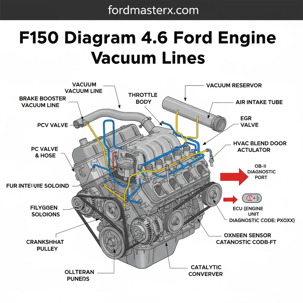
F150 Diagram 4.6 Ford Engine Vacuum Lines: Step-by-Step
The f150 diagram 4.6 ford engine vacuum lines illustrates the routing between the intake manifold, EGR valve, and EVAP canister. Using this map helps identify cracked hoses causing a check engine light or lean diagnostic code. Proper routing ensures the ECU can manage idle speed and emissions systems effectively.
📌 Key Takeaways
- Provides a visual map from the intake manifold to emission sensors
- The DPFE sensor and EGR valve are the most critical components to verify
- Engine must be completely cool before handling brittle rubber lines
- A smoke machine is the best tool for finding small vacuum leaks
- Essential for diagnosing rough idle or poor fuel economy issues
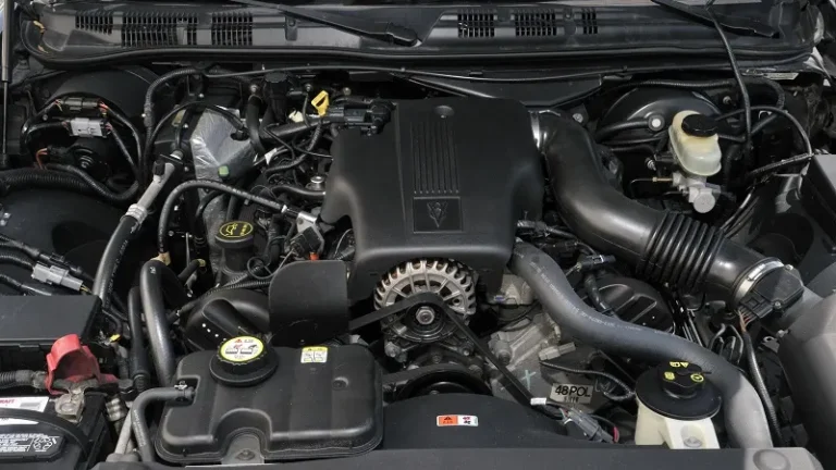
Finding yourself staring at a complex web of rubber hoses and plastic connectors under the hood of your truck can be overwhelming, especially when your engine is idling poorly or stalling. If you are dealing with a rough idle, a sudden drop in fuel economy, or a persistent “lean” condition, referencing an accurate f150 diagram 4.6 ford engine vacuum lines is the most critical step in your repair process. The 4.6L Triton V8 is a legendary engine, but its performance relies heavily on a precise balance of air pressure and vacuum signals. This article serves as a comprehensive guide to identifying every line, understanding how these systems interact with your vehicle’s computer, and providing you with the technical confidence to restore your Ford’s factory performance.
Vacuum lines are essentially the “nervous system” of your 4.6L engine. They transmit physical pressure signals to various sensors and actuators, allowing the ECU to make real-time adjustments to the air-fuel mixture and ignition timing.
The primary f150 diagram 4.6 ford engine vacuum lines illustrates a closed-loop system where the intake manifold serves as the central vacuum reservoir. On this specific engine, you will notice three major “circuits.” The first is the PCV (Positive Crankcase Ventilation) system, which typically features a thick rubber or rigid plastic hose running from the passenger-side valve cover to the rear of the intake manifold. The second circuit is the EGR (Exhaust Gas Recirculation) system, which uses a vacuum regulator solenoid to open a valve that allows exhaust gases back into the combustion chamber. This system is easily identified by the small-diameter green or red plastic lines. The third circuit involves the EVAP (Evaporative Emission) system, which pulls fuel vapors from the gas tank through a charcoal canister and into the intake via a purge valve.
[DIAGRAM_PLACEHOLDER: A detailed technical illustration of a 4.6L Ford V8 engine bay. Key components labeled: A. Intake Manifold Vacuum Port, B. PCV Valve and Hose, C. EGR Vacuum Regulator, D. DPFE Sensor, E. Brake Booster Vacuum Supply, F. EVAP Purge Valve, G. IWE Solenoid (for 4×4 models). Lines are color-coded: Green for EGR, Red for Main Vacuum, Black for PCV/EVAP.]
In the diagram, you will also see the vacuum supply for the brake booster, which is usually the largest diameter hose in the system, reinforced to handle high pressure. For those with four-wheel-drive models, the diagram includes a dedicated line running to the IWE (Integrated Wheel End) solenoids located near the firewall. These lines are critical because a leak here will cause your front hubs to engage partially while driving, leading to a grinding noise. Most 4.6L Ford engines utilize color-coded plastic lines: green usually indicates the EGR signal, red or white represents the main vacuum supply from the reservoir, and black or blue often handles the EVAP or auxiliary controls. Understanding these variations is vital because the routing can shift slightly depending on whether your truck is a base model or a fully loaded 4×4.
Never attempt to diagnose vacuum leaks while the engine is overheating or if you notice leaking fuel. Vacuum lines are often located near the accessory belt and timing chain cover; keep loose clothing and fingers away from moving parts while the engine is running.
Navigating the vacuum routing on a 4.6L Ford engine requires a systematic approach. Follow these steps to properly read the diagram and inspect your system:
- ✓ Locate the VECI Label: Look for the Vehicle Emission Control Information (VECI) sticker located on the underside of the hood or on the radiator shroud. This is your truck’s “birth certificate” for vacuum routing and complements the general diagram provided here.
- ✓ Identify the Main Source: Find the large vacuum tree or port on the upper intake manifold. Every vacuum-operated component on the 4.6L engine gets its “pull” from this centralized location.
- ✓ Track the PCV Circuit: Follow the thickest hose from the manifold to the passenger side valve cover. Inspect the rubber elbow at the back of the manifold, as this is the most common failure point on the 4.6L engine due to oil-induced rot.
- ✓ Examine the EGR and DPFE: Find the EGR valve (a metal saucer-shaped component). Follow the thin green line back to the EGR Vacuum Regulator (EVR). Ensure the lines connecting to the DPFE sensor (a rectangular plastic box with two silicone hoses) are not swapped, as this will trigger a diagnostic code immediately.
- ✓ Test the Brake Booster: Locate the large hose running to the round black drum on the driver’s side firewall. Ensure the check valve at the booster is tight and the hose has no cracks.
- ✓ Verify 4×4 Lines (if applicable): Trace the lines from the solenoid on the firewall down toward the front wheels. These are often damaged by road debris or heat from the coolant flow hoses.
- ✓ Use a Vacuum Pump: If a line looks suspect, use a handheld vacuum pump to see if it holds pressure. If the gauge drops, the line or the component it attaches to is leaking.
To perform these checks successfully, you will need a few basic tools: a flashlight, long-nose pliers for reaching deep into the engine bay, a handheld vacuum tester, and perhaps a small mirror to see the ports behind the intake manifold. When working near the manifold, be mindful of the torque spec for any bolts you may need to loosen; over-tightening plastic manifold components can lead to permanent air leaks that a vacuum diagram cannot fix.
Common issues with the 4.6L vacuum system often manifest as a “Lean” diagnostic code (P0171 or P0174) stored in the ECU. When air enters the engine through a cracked vacuum line rather than the throttle body, the OBD-II system detects too much oxygen and triggers the check engine light. Another frequent problem is a “soft” or “hard” brake pedal, which points directly to a failure in the brake booster supply line. Furthermore, if your 4.6L engine experiences a sudden “hunting” idle where the RPMs bounce up and down, it is almost certainly a leak in the PCV elbow or the EVAP purge line.
The diagram is your primary tool for solving these issues because it allows you to isolate systems. For example, by temporarily plugging the main vacuum port for the EVAP system, you can determine if that specific circuit is causing your rough idle. If the idle smooths out with the line capped, you know the leak is downstream in that circuit. If you find that your 4×4 hubs are making a clicking noise, the diagram helps you locate the vacuum reservoir—a small plastic box often hidden in the fender well—which frequently cracks over time.
If you are replacing old, brittle plastic lines, consider upgrading to high-temp silicone vacuum tubing. Silicone is much more resistant to the extreme heat generated by the 4.6L V8 and will not become brittle or crack like the factory nylon lines.
When maintaining your 4.6L Ford engine, treat vacuum lines as a wear item. Every time you perform an oil change or check your accessory belt, take a moment to wiggle the vacuum elbows. If your fingers come away with black soot, the rubber is degrading and needs replacement. It is also wise to check the proximity of these lines to the coolant flow pipes. Over time, the heat cycles from the cooling system can bake the vacuum lines, making them snap at the slightest touch.
Cost-saving advice: instead of buying expensive pre-bent factory vacuum harnesses, you can often repair sections of a line using standard rubber vacuum hose of the same inner diameter. Simply cut out the cracked section and join the two ends with a connector or a snug-fitting piece of rubber hose. However, always ensure that the internal diameter matches the f150 diagram 4.6 ford engine vacuum lines specifications to maintain the correct signal strength to the ECU.
By using this f150 diagram 4.6 ford engine vacuum lines guide, you can eliminate the guesswork that leads to expensive “parts cannon” repairs. Whether you are chasing a check engine light or simply performing preventative maintenance, understanding the vacuum architecture is the key to keeping your truck on the road. A well-sealed vacuum system ensures that your timing chain stays synchronized with the engine’s load and that your OBD-II system remains free of frustrating diagnostic codes. Take your time, trace each line carefully, and your 4.6L Triton will continue to provide the reliable service it is known for.
Frequently Asked Questions
Where is the EGR valve located?
On the 4.6L engine, the EGR valve is typically located at the upper rear of the intake manifold, near the firewall. It is a round metal component connected to a vacuum line and a stainless steel tube. Correct placement is vital for the ECU to regulate exhaust gas flow properly.
What does the vacuum line diagram show?
The f150 diagram 4.6 ford engine vacuum lines shows the precise routing of rubber and plastic tubes that transport vacuum pressure. It connects the throttle body to the brake booster, PCV valve, and EVAP system. This visual guide is essential for diagnosing leaks that trigger a check engine light.
How many vacuum connections does the intake have?
The 4.6L intake manifold features several vacuum ports, typically ranging from four to six primary connections. These include the main vacuum tree, the PCV port, and lines leading to the fuel pressure regulator. Each must be sealed tightly to avoid a diagnostic code related to lean fuel mixtures.
What are the symptoms of a bad vacuum line?
Common symptoms include a rough idle, stalling at stoplights, and a significant drop in fuel economy. You may also hear a distinct hissing sound from the engine bay. These leaks often trigger a check engine light and a specific diagnostic code like P0171 or P0174 on your OBD-II scanner.
Can I replace these vacuum lines myself?
Yes, replacing vacuum lines is a straightforward DIY task that requires minimal tools. By following the f150 diagram 4.6 ford engine vacuum lines, you can swap out brittle plastic for high-quality silicone hoses. It is a cost-effective way to restore engine performance and ensure the ECU receives accurate readings.
What tools do I need for vacuum line repair?
You will need needle-nose pliers, a utility knife for cutting new hose, and an OBD-II scanner to clear codes. While most lines don’t require specialized tools, some mounting brackets may require a small socket set. Always check for a specific torque spec if you are removing the intake manifold.