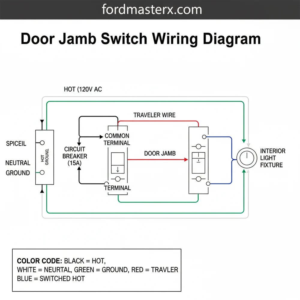
Door Jamb Switch Wiring Diagram: Easy Setup Guide
A door jamb switch wiring diagram illustrates how to connect the switch to your interior lighting circuit. Typically, the hot wire connects to the common terminal, while the traveler wire runs to the light fixture. The ground wire attaches to the metal frame, completing the safety path for the electrical system.
📌 Key Takeaways
- Explains the electrical path from the power source to the door-activated light
- Identifying the common terminal is essential for proper switch operation
- Always ensure the ground wire is securely fastened to prevent electrical shocks
- Use this diagram to troubleshoot flickering or non-functional interior door lights
- Ideal for installing new closet lights or replacing faulty automotive door sensors
The door jamb switch, often referred to as a “door trigger” or “pin switch,” is a deceptively simple component that plays a critical role in your vehicle’s convenience and security systems. Whether you are troubleshooting a dome light that refuses to turn off, installing an aftermarket alarm, or adding custom LED floor lighting, understanding the door jamb switch wiring diagram is essential. These small plunger-style switches act as the primary sensor for the vehicle to know whether a door is open or closed, sending signals that affect interior lighting, door-ajar warnings, and even ignition interlocks in some modern vehicles.
For the DIY enthusiast, working with these switches requires more than just a pair of wire strippers; it requires an understanding of electrical polarity and circuit logic. Because most vehicles utilize a “ground-side” switching system, the way you read a diagram and test the wires differs significantly from standard power-based circuits. This guide provides a deep dive into the architecture of door jamb circuits, helping you navigate the wires with confidence and precision.
Main Components and Features
To interpret a door jamb switch wiring diagram, you must first recognize the physical and electrical components involved. While designs vary between manufacturers like Ford, GM, and Toyota, the fundamental mechanics remain relatively consistent.
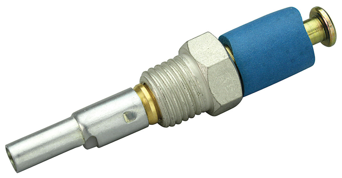
- The Plunger (The Actuator): This is the spring-loaded button that is depressed when the door is closed. When the door opens, the spring pushes the plunger out, changing the state of the internal electrical contacts.
- The Switch Housing: Usually made of plastic or metal, the housing often serves as the mounting point. In older “single-wire” systems, the metal housing itself acts as the ground contact when screwed into the vehicle’s chassis.
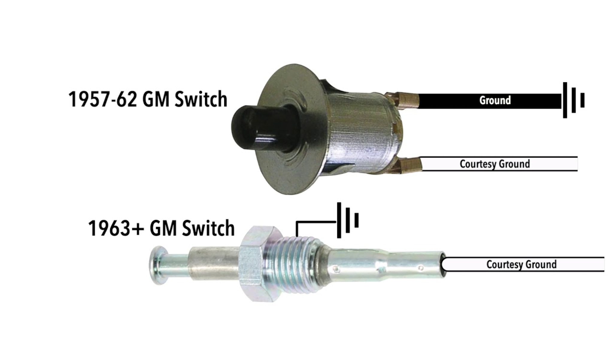
- Wiring Harness/Connector: Depending on the vehicle’s age, you will find either one or two wires exiting the back of the switch.
- Single-Wire Systems: Common in classic cars. The switch provides a ground path through its mounting screw. The single wire is the “trigger” wire connected to the light.
- Two-Wire (or more) Systems: Common in modern vehicles. One wire provides a ground or reference signal, and the other sends that signal back to a computer (BCM).
- The Load (Interior Lights): The final destination of the circuit. In a standard setup, the door jamb switch completes the circuit that allows the dome light to illuminate.
In terms of measurements, most door jamb switches are designed to fit into a hole roughly 1/2 inch (12.7mm) to 3/4 inch (19mm) in diameter. The travel distance of the plunger is typically between 1/4 inch and 1/2 inch. Knowing these measurements is vital if you are replacing a factory switch with a universal aftermarket version.
How to Use and Read a Door Jamb Switch Wiring Diagram
Reading a wiring diagram is like reading a map of a city’s plumbing. You need to follow the flow of electricity from the power source (the battery) to the destination (the ground). In most door jamb diagrams, you will encounter two primary types of circuit logic: Negative Trigger and Positive Trigger.
1. Negative Trigger (Ground-Side Switching)
This is the most common configuration in the automotive world. In a negative trigger diagram, the interior light is already supplied with 12V constant power. The door jamb switch sits on the ground side of the circuit. When the door opens, the switch closes its internal contact, connecting the circuit to the vehicle’s chassis (ground).
On the diagram: Look for a wire leading from the light bulb symbol to a switch symbol, which then leads to a “ground” symbol (a series of decreasing horizontal lines).
2. Positive Trigger (Power-Side Switching)
Though less common, some vehicles (notably older Fords and some Chryslers) use a positive trigger. In this setup, the light is always grounded, and the door jamb switch completes the 12V power path to the bulb.
On the diagram: You will see the switch located between the fuse/battery source and the light bulb.
Common Wire Colors and Locations
While colors vary by manufacturer, there are some industry “standards” you might encounter in diagrams:
- General Motors (GM): Often uses a 20-gauge or 22-gauge Grey or Tan wire for the door trigger.
- Toyota/Lexus: Frequently uses Red/White or Green/Black wires.
- Ford: Often uses Black/Light Blue or Yellow/Black.
- Ground Wires: Almost universally Black, though in single-wire switches, the “ground” is the uninsulated metal body of the switch itself.
Practical Installation and DIY Tips
If you are adding a new switch or replacing a broken one, follow these practical steps to ensure a clean installation:
- Identify the Polarity: Use a multimeter. Set it to DC Volts. Probe the wire at the switch. If you see 12V when the door is open (and the light is on), it is likely a positive trigger. If you see 0V but the light is on, it is likely a negative trigger (the wire is now grounded).
- Check for Continuity: Switch your multimeter to the “Ohm” or “Continuity” (beep) setting. Place one lead on the switch terminal and the other on a bare metal part of the car’s frame. When the plunger is out (door open), the meter should beep. When the plunger is pushed in (door closed), the beep should stop.
- Protect the Connection: Door jambs are prone to moisture. Use heat-shrink tubing over your wire connections rather than just electrical tape. This prevents corrosion which can cause the lights to flicker or stay on indefinitely.
- Adjusting the Plunger: Many aftermarket switches have “self-adjusting” plungers. You install them, and the first time you close the door, the door frame pushes the plunger to the exact length needed. Be careful not to manually push these in too far before installation.
Troubleshooting Common Issues
Door jamb switch circuits are notorious for failing due to their exposure to the elements and physical wear. Here is how to troubleshoot the most common problems found on a wiring diagram.
The Interior Lights Won’t Turn On
If the diagram shows the switch completes the ground, but the lights won’t turn on, the most likely culprit is a corroded contact. Remove the switch and check the mounting screw. In single-wire systems, if the screw is rusty, the switch cannot ground to the chassis. Clean the metal with a wire brush and reinstall.
The Interior Lights Won’t Turn Off
This usually indicates a “short to ground.” Somewhere between the light and the switch, the wire’s insulation has rubbed off and is touching the metal frame of the car. Refer to your wiring diagram to identify the wire color and trace it along the kick panel to look for pinched spots. Another possibility is a broken internal spring in the switch, keeping the circuit closed even when the plunger is depressed.
The “Door Ajar” Warning Stays On (Modern Vehicles)
On modern cars, the door jamb switch is often integrated into the door latch assembly inside the door itself, rather than a visible plunger on the jamb. If your diagram shows the switch leads into the “Latch Assembly,” you may need to spray the latch with electrical contact cleaner or a specialized lubricant. Often, gunk builds up in the latch, preventing the tiny internal micro-switch from clicking over.
Summary of Circuit Logic
To finalize your understanding, remember the “Logic Gate” of the door jamb switch. For most cars, the circuit follows this path:
Battery (+) → Fuse → Dome Light Filament → Door Jamb Switch → Vehicle Chassis (Ground)
When the door is closed, the switch is “Open” (breaking the path). When the door is open, the switch is “Closed” (completing the path). By mastering this simple flow and cross-referencing it with your specific vehicle’s wiring diagram, you can solve nearly any interior lighting or security trigger issue with ease.
Step-by-Step Guide to Understanding the Door Jamb Switch Wiring Diagram: Easy Setup Guide
Identify the circuit wires including the hot wire, neutral wire, and ground wire coming from the power source.
Locate the common terminal on the back of the door jamb switch to prepare for the main connection.
Understand how the traveler wire connects the switch to the light fixture in the ceiling or wall.
Connect the hot wire to the common terminal and attach the traveler wire to the secondary terminal.
Verify that the ground wire is properly bonded to the electrical box or the switch’s ground screw.
Complete the installation by mounting the switch in the door frame and testing the door’s operation.
Frequently Asked Questions
Where is the door jamb switch located?
The door jamb switch is typically located on the hinged side of the door frame or near the latch. In vehicles, it is often found in the pillar between the front and rear doors. In homes, it is usually mounted inside the frame of a closet door or pantry door.
What does a door jamb switch wiring diagram show?
The diagram shows the electrical layout of the switch, including the power source connection and the path to the light fixture. It details how the circuit opens and closes when the door moves, highlighting the specific connections for the traveler wire, hot wire, and neutral wire within the system.
How many wires does a door jamb switch have?
Most standard door jamb switches feature two or three wires. A two-wire setup usually involves a hot wire and a traveler wire. A three-wire setup often includes a ground wire or a neutral wire connection to ensure the circuit is properly grounded for safety and to prevent electrical interference.
What are the symptoms of a bad door jamb switch?
Common symptoms include lights that stay on when the door is closed, lights that fail to turn on at all, or flickering when the door moves. If the switch feels stuck or does not spring back when pressed, it likely needs replacement or cleaning to restore proper circuit contact.
Can I install this myself?
Yes, installing a door jamb switch is a common DIY task. However, you must turn off the power at the breaker first. Following a door jamb switch wiring diagram makes the process straightforward, provided you have basic electrical knowledge and the right tools to safely handle the wiring connections.
What tools do I need for this task?
You will need a screwdriver to remove the old switch, a wire stripper for preparing the ends of the traveler wire and hot wire, and a voltage tester to ensure the power is off. A multimeter can also help verify continuity within the switch itself during the troubleshooting process.