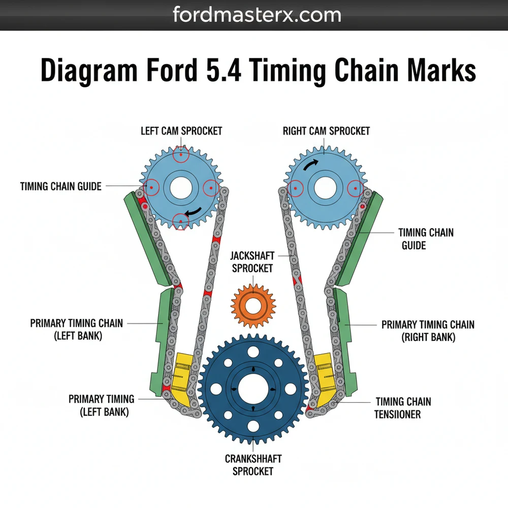
Diagram Ford 5.4 Timing Chain Marks: Alignment Guide
The diagram Ford 5.4 timing chain marks illustrate the alignment of the crankshaft and camshaft gears. You must align the single dark links on the chains with the timing marks on the sprockets while the crankshaft keyway sits at the proper orientation to ensure the entire valve train system is synchronized.
📌 Key Takeaways
- Main purpose: Precise engine synchronization for the 5.4L Triton engine.
- Most important component: The crankshaft sprocket keyway and marked chain links.
- Safety: Ensure the engine is at TDC (Top Dead Center) to avoid valve-to-piston contact.
- Practical tip: Use a paint pen to highlight marks on the chain for easier visual confirmation.
- When to use: During timing chain replacement or internal engine overhaul.
Successfully navigating a complex engine overhaul requires more than just mechanical skill; it requires an exact visual roadmap. When you are working on the Ford 5.4L Triton engine, specifically the 3-valve variant, the margin for error is virtually non-existent because this is an interference engine. Utilizing a precise diagram ford 5.4 timing chain marks is the only way to ensure that the valves and pistons do not collide during operation. This article provides a comprehensive overview of the timing system, detailing how to interpret the alignment marks, the configuration of the chains, and the step-by-step process to ensure your engine’s internal rhythm is perfectly synchronized for peak performance and longevity.
The Ford 5.4L engine relies on a dual-chain system. The “Left” (Driver side) and “Right” (Passenger side) designations are always determined from the perspective of sitting in the driver’s seat, not standing in front of the bumper.
The Anatomy of the Timing System Layout
The timing system on the Ford 5.4L engine is a sophisticated mechanical structure designed to synchronize the rotation of the crankshaft with the two overhead camshafts. At the heart of this layout are the timing marks, which act as the blueprint for the entire assembly. The schematic involves several primary components: the crankshaft sprocket, two long timing chains, two hydraulic tensioners, and the camshaft phasers located at the top of the engine.
When looking at a standard diagram ford 5.4 timing chain marks, you will notice that each chain has distinct “dark” or “colored” links. Usually, there are two colored links together at one end and a single colored link at the other. These are not decorative; they are critical indicators for the system configuration. The single colored link is intended to align with the mark on the crankshaft sprocket, while the pair of colored links straddles the timing mark on the camshaft phasers.
The camshaft phasers themselves are large circular components that vary the valve timing. On a 3-valve engine, the phasers are marked with an “L” and an “R.” A common point of confusion is that both phasers are often identical parts, but they feature both marks. You must align the chain to the “L” mark on the driver’s side and the “R” mark on the passenger side. The crankshaft sprocket features a single dot or dimple, which must be positioned at the 6 o’clock position during the initial setup to ensure the pistons are in the safe zone.
Interpreting the Schematic and Component Identification
The structural overview of the 5.4 timing system reveals a mirrored layout. The left bank (Bank 2) and the right bank (Bank 1) use different guide configurations. The guides are long, curved plastic and metal pieces that prevent the chain from whipping or skipping. The tensioners, which are usually cast iron or high-grade plastic, use oil pressure to maintain the tight layout. Understanding the schematic means recognizing that the chain path is not perfectly symmetrical; the passenger side chain sits behind the driver side chain on the crankshaft sprocket.
Never rotate the crankshaft or camshafts independently once the chains are removed unless the instructions specifically state the engine is in a “neutral” position. Doing so can cause the valves to strike the piston heads, leading to catastrophic engine failure.
Step-by-Step Guide to Using the Timing Marks Diagram
Applying the information from the diagram to a real-world engine requires a disciplined, step-by-step approach. Before beginning, ensure you have a specialized camshaft holding tool and a crankshaft positioning tool, as these make the process significantly more accurate.
- ✓ Step 1: Position the Crankshaft. Rotate the crankshaft until the keyway is at the 12 o’clock position and the timing dimple on the sprocket is at the 6 o’clock position.
- ✓ Step 2: Prepare the Chains. Lay your chains out on a flat surface. Fold them in half to find the exact opposite ends. Mark the single link at one end and the pair of links at the other with a paint pen if the factory colors have faded.
- ✓ Step 3: Align the Passenger Side (Bank 1). Place the single colored link on the crankshaft sprocket timing mark (6 o’clock). Drape the chain up to the passenger side phaser. Align the two colored links so they straddle the “R” mark on the phaser.
- ✓ Step 4: Align the Driver Side (Bank 2). Similarly, place the single colored link of the second chain on the crankshaft sprocket mark. Drape this chain to the driver side phaser and align the two colored links so they straddle the “L” mark.
- ✓ Step 5: Install Guides and Tensioners. Secure the stationary guides first, then the pivoting guides. Install the tensioners. If you are using original-style tensioners, you will need to pull the grenades-style locking pin to apply tension to the system.
- ✓ Step 6: Verify the Configuration. Double-check all marks. The single links should still be at 6 o’clock on the crank, and the double links should perfectly frame the “L” and “R” marks on the respective phasers.
- ✓ Step 7: Manual Rotation. Use a breaker bar to rotate the crankshaft two full 360-degree turns by hand. This ensures there is no mechanical interference. Note: The colored links will not align with the marks again for many rotations; this is normal.
Common Issues & Troubleshooting
Even with a detailed diagram ford 5.4 timing chain marks, technicians often encounter hurdles. One of the most frequent problems is “chain slap,” which occurs when the plastic guides shatter or the tensioners lose hydraulic pressure. If you notice a rattling sound upon startup that disappears after a few seconds, your tensioner seals may be failing, allowing oil to drain back when the engine is off.
The diagram is instrumental in solving synchronization codes like P0011 (Bank 1 over-advanced) or P0022 (Bank 2 over-retarded). These codes often indicate that the timing has skipped a tooth or the VCT (Variable Cam Timing) solenoid is clogged with debris. If your marks do not align perfectly during the installation phase, do not attempt to “close enough” the timing. Even being off by one tooth on the sprocket can cause rough idling, poor fuel economy, and eventual valve damage.
When installing the phasers, ensure the dowel pin on the camshaft is properly seated in the phaser slot. It is possible to bolt the phaser on incorrectly, which will throw off the entire timing configuration regardless of where the chain marks are.
Tips & Best Practices for Timing Maintenance
To ensure the longevity of your 5.4L engine after following the timing blueprint, maintenance is paramount. The timing system in these engines is notoriously sensitive to oil pressure and cleanliness. The VCT solenoids have very fine screens that can easily become clogged if oil changes are neglected.
We recommend using a high-quality full synthetic oil and a motorcraft filter with a silicone anti-drain back valve. This keeps oil in the upper galleries, ensuring that the tensioners have immediate pressure upon startup. Furthermore, many enthusiasts suggest upgrading to cast iron tensioners from older 2-valve models, as they do not use the rubber seals that frequently blow out on the 3-valve plastic tensioners.
When purchasing parts, avoid “no-name” timing kits. The 5.4L engine’s structure demands components that meet exact OEM specifications. Using a sub-par phaser or a chain that stretches prematurely will lead to repeating this labor-intensive job within a few thousand miles. Always clean the oil pan and the oil pickup tube screen while the front cover is off; debris from broken plastic guides often settles there and can starve the new timing components of the lubrication they need to function.
By strictly following the diagram ford 5.4 timing chain marks and maintaining a clean oiling system, you can effectively eliminate the “Triton Tick” and keep your vehicle running smoothly for hundreds of thousands of miles. Timing is the heartbeat of your engine; treat the schematic with the precision it deserves, and your mechanical efforts will be rewarded with a reliable, powerful drive.
Frequently Asked Questions
Where is the crankshaft timing mark located?
The crankshaft timing mark is located on the crankshaft sprocket, specifically at the 6 o’clock position when the keyway is at roughly 11 o’clock. This specific configuration is crucial for setting the base timing before installing the chains and ensuring the internal structure is properly aligned.
What does the timing chain marks diagram show?
This diagram shows the exact relationship between the crankshaft and camshaft sprockets. It illustrates how the colored links on the timing chain must correspond to the stamped marks on the gears, providing a visual structure for the entire valve timing system to prevent catastrophic engine failure.
How many marked links does the 5.4 timing chain have?
Each timing chain typically features three distinct dark or colored links used for alignment. Two links are grouped together to straddle the camshaft sprocket mark, while a single link at the opposite end of the chain structure aligns perfectly with the mark on the crankshaft sprocket.
What are the symptoms of bad timing chain alignment?
Symptoms of poor timing configuration include rough idling, engine misfires, and a lack of power. If the chain skips a tooth, you may hear metallic rattling or experience ‘limp mode.’ In severe cases, incorrect alignment of the system components leads to bent valves or piston damage.
Can I replace the Ford 5.4 timing chain myself?
Replacing this system is a complex task that requires advanced mechanical knowledge and specific tools, such as camshaft holding brackets. While a dedicated DIYer can perform the replacement using a clear diagram, any error in the component layout can result in permanent and expensive engine destruction.
What tools do I need for timing chain alignment?
You will need a standard socket set, a torque wrench, a harmonic balancer puller, and Ford-specific timing tools like the camshaft positioning tool. These tools ensure the internal structure remains stationary while you align the timing chain marks according to the manufacturer’s specified engine layout.