Delphi Fuel Pump Wiring Diagram: Easy Setup Guide
A Delphi fuel pump wiring diagram illustrates the electrical connections for the pump motor and fuel level sender. It typically identifies the hot wire for power, the ground wire for the return circuit, and signal wires for the sending unit, ensuring the relay properly activates the pump for consistent fuel pressure.
📌 Key Takeaways
- Properly identifies the pinout for power, ground, and sensor leads
- The ground wire is the most critical connection for circuit completion
- Always disconnect the battery before handling fuel system electricals
- Use a multimeter to check voltage drop at the connector pins
- Essential for diagnosing fuel gauge inaccuracies or pump failure
When you are faced with a vehicle that refuses to start or stalls unexpectedly, having access to an accurate delphi fuel pump wiring diagram is the difference between a quick fix and hours of frustration. Delphi fuel modules are precision-engineered components, and their electrical interfaces are designed to handle specific current loads to ensure consistent fuel pressure. A correct diagram allows you to identify which pin provides power and which manages the fuel level sensor signal. This guide will walk you through the complexities of Delphi wiring, helping you master terminal identification, wire color codes, and voltage testing procedures.
Understanding the Delphi Fuel Pump Wiring Diagram Layout
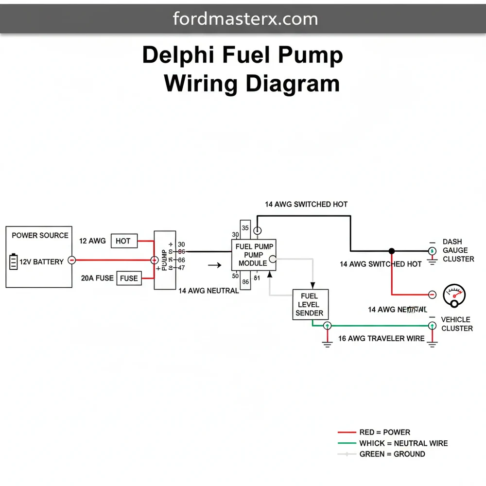
A delphi fuel pump wiring diagram typically illustrates a four-pin or five-pin connector configuration. Unlike simple electrical circuits, an automotive fuel pump system serves two primary functions: powering the high-speed electric motor and sending resistance data to the fuel gauge. To accommodate these needs, the diagram distinguishes between heavy-duty power lines and sensitive signal lines.
The primary components in the diagram include the hot wire, which delivers 12-volt power from the fuel pump relay, and the ground wire, which completes the circuit to the vehicle chassis. In many Delphi configurations, the connector is labeled with letters (A, B, C, D). Usually, the larger gauge wires located at pins A and B are dedicated to the motor. These wires must be of a specific thickness to prevent overheating and voltage drop.
The signal wires, often smaller in gauge, connect to the fuel level sending unit. While household systems might refer to a neutral wire, in an automotive DC circuit, the return path is always through the ground wire. The diagram will also show the relationship between the fuel pump and the common terminal on the relay. This common terminal acts as the junction point that switches between the “prime” state and the “run” state.
In Delphi wiring, the terminal pins are often plated with specific metals to prevent corrosion. When identifying wires, always match the pin letter on the plastic connector housing to the corresponding line on your wiring schematic to avoid reversing polarity.
Variations in these diagrams occur based on whether the vehicle uses a return-style or returnless fuel system. In some advanced Delphi modules, a fifth wire might be present to act as a traveler wire for a fuel pressure sensor, sending real-time data back to the Engine Control Module (ECM) to regulate pump speed. Understanding these nuances ensures that you are not just connecting wires, but restoring the engineered logic of the fuel system.
How to Interpret and Implement the Delphi Fuel Pump Wiring Diagram

Reading a delphi fuel pump wiring diagram requires a methodical approach to ensure the electrical integrity of the fuel system. Following a structured sequence prevents accidental shorts that could damage the vehicle’s ECM or blow expensive fuses.
Step 1: Identify Wire Gauge and Purpose
Before making any connections, examine the physical wires on your harness. The hot wire and the ground wire for the pump motor will be significantly thicker (usually 14 or 16 gauge) than the sensor wires (often 18 or 20 gauge). The wiring diagram will denote these differences using line thickness or specific numerical labels. Using a wire with an insufficient gauge can lead to a significant voltage drop, causing the pump to run slow or fail prematurely.
Step 2: Locate the Common Terminal on the Relay
Refer to your vehicle’s fuse box diagram alongside the pump schematic. The fuel pump relay has a common terminal that connects to the pump’s hot wire. When the ignition is turned on, the relay closes, allowing voltage to flow from the battery to the pump. Verify that the wire color leaving the relay matches the wire color entering the fuel pump connector according to the diagram.
Step 3: Establish a Solid Ground Connection
The ground wire is arguably the most important part of the circuit. In many aftermarket or custom installations, this wire is secured to a metal stud or a brass screw on the chassis. The wiring diagram will show the ground path terminating at a specific ground point (G-point). Ensure this connection is clean, tight, and free of paint or rust to maintain a low-resistance path.
Never swap the hot wire and ground wire on the pump motor pins. While the motor might spin backwards in some designs, it can also lead to internal damage or spark hazards near the fuel tank.
Step 4: Connect the Fuel Level Sensor Lines
The remaining two wires in a standard Delphi 4-pin connector are for the fuel level sender. These do not carry high voltage. Instead, they operate on a 5-volt reference or a variable resistance to ground. Following the diagram, connect these to the sensor input on the dashboard or ECM. While these might resemble a traveler wire in house wiring due to their signal-switching nature, they are strictly low-voltage DC signals.
Step 5: Verify Voltage and Continuity
With the wiring in place, use a digital multimeter to test the circuit. Turn the key to the “ON” position (without cranking) and measure the voltage at the pump connector. You should see a reading close to battery voltage (12.6V) for a few seconds as the system primes. If the voltage is low, re-check the gauge of your wires and the integrity of the common terminal at the relay.
Step 6: Secure the Harness
Once the electrical tests pass, secure the wires away from the fuel lines and moving suspension parts. Use automotive-grade plastic loom to protect the hot wire from chafing against the chassis, which could cause a fire hazard.
Troubleshooting Common Wiring Failures

Even with a perfect delphi fuel pump wiring diagram, issues can arise due to environmental factors or age. The most frequent problem is high resistance at the connector pins. Over time, heat and moisture can corrode the terminals, leading to a situation where the pump receives some voltage but not enough current to operate under load.
- ✓ Burnt Connector Pins: Often caused by an aging pump drawing too much amperage through a wire gauge that is too small.
- ✓ Intermittent Ground: If the ground wire is attached to a loose brass screw or rusty frame section, the pump may cut out while driving.
- ✓ Relay Failure: A worn common terminal inside the fuel pump relay can click without actually passing current to the pump.
- ✓ Sensor Logic Error: If the fuel gauge reads empty despite a full tank, the signal wires might be swapped or shorted to a neutral wire reference point.
If you experience a “crank but no start” condition, use your diagram to perform a “bypass test” by jumping the relay common terminal to a 12V source. If the pump runs, the issue lies in the control side of the circuit (ECM or relay) rather than the pump or its direct wiring.
Best Practices for Fuel System Wiring Maintenance
To ensure the longevity of your Delphi fuel pump, follow professional maintenance and installation standards. Electrical health is just as important as fuel quality when it comes to the life of the pump motor.
Always use dielectric grease on the connector pins before plugging the harness into the Delphi module. This prevents moisture from entering the terminal housing and causing electrolysis-induced corrosion.
When replacing a pump, it is highly recommended to replace the connector pigtail as well. Many Delphi fuel pump kits include a new harness for this reason. When splicing the new pigtail, use heat-shrink butt connectors. Standard electrical tape is not sufficient in an automotive environment because fuel vapors and road heat can degrade the adhesive, exposing the hot wire and potentially causing a short circuit.
Always verify the gauge of the wire you are using if you need to extend the harness. Many modern vehicles have moved toward thinner, weight-saving wires, but for a high-performance fuel pump, thicker is almost always better. A drop of just one volt can reduce fuel flow by up to 10%, which can lead to a lean engine condition and potential damage.
By strictly following the delphi fuel pump wiring diagram and ensuring every ground wire and hot wire is properly crimped and insulated, you guarantee a reliable fuel delivery system. Proper wiring is the foundation of vehicle performance, and taking the time to map out every common terminal and signal path will pay off in long-term vehicle reliability.
Step-by-Step Guide to Understanding the Delphi Fuel Pump Wiring Diagram: Easy Setup Guide
Identify the harness connector pins using the delphi fuel pump wiring diagram to distinguish the motor power from sensor lines.
Locate the hot wire and neutral wire (ground) on the vehicle-side harness to verify that the relay is sending voltage.
Understand how the traveler wire or signal leads send resistance data from the float arm to the instrument cluster.
Connect the multimeter to the common terminal and ground wire to test for proper electrical resistance across the sending unit.
Verify that all pins are free of corrosion and that the connector snaps firmly into the Delphi pump housing.
Complete the installation by reconnecting the battery and cycling the ignition to prime the fuel system and check for leaks.
Frequently Asked Questions
Where is the Delphi fuel pump located?
The fuel pump is typically located inside the fuel tank. Access is usually gained through an opening under the rear passenger seat or by lowering the fuel tank from the vehicle’s chassis. Correct location identification is essential before using the wiring diagram for any diagnostic or replacement work.
What does a Delphi fuel pump wiring diagram show?
This diagram displays the circuit paths between the fuel pump, the relay, and the PCM. It highlights which wires carry the 12V hot wire current to the motor and which serve as the ground wire or signal leads for the fuel level sender and pressure sensor systems.
How many wires does a Delphi fuel pump have?
Most Delphi assemblies use a four or five-pin connector. This includes a high-gauge hot wire for the motor, a ground wire, two signal wires for the fuel level sensor, and sometimes an additional traveler wire or common terminal for an integrated fuel tank pressure sensor on EVAP systems.
What are the symptoms of a bad Delphi fuel pump?
Symptoms include engine sputtering at high speeds, difficulty starting, or a complete no-start condition. If the fuel gauge is erratic, the wiring diagram can help determine if the issue is a faulty ground wire or a problem with the internal sender unit’s resistance range.
Can I replace a Delphi fuel pump myself?
Yes, replacement is feasible for many DIYers with basic tools. However, working with fuel requires extreme caution. Using a delphi fuel pump wiring diagram ensures that the electrical harness is correctly seated and that no wires are pinched during the reinstallation of the fuel tank assembly.
What tools do I need for fuel pump testing?
You will need a digital multimeter to test for 12V power at the hot wire and continuity on the ground wire. Additionally, a fuel pressure gauge is necessary to verify the pump’s mechanical output, while a basic socket set and fuel line disconnect tools are needed for removal.