6.4 Powerstroke Vacuum Line Diagram: Easy Setup Guide
The 6.4 Powerstroke vacuum line diagram outlines the pneumatic connections between the pump, reservoir, and HVAC actuators. It is essential for diagnosing why the blower motor won’t switch vents or if the AC compressor isn’t cycling correctly. Correct routing ensures vacuum reaches the blend door to move air across the evaporator.
📌 Key Takeaways
- Routes vacuum pressure to HVAC actuators and 4WD hubs
- The vacuum pump is the primary source of system pressure
- Always check for brittle or cracked lines near the engine heat
- Use a vacuum gauge to isolate leaks in specific branches
- Refer to this diagram when air only blows from the defrost vents
Navigating the complexities of your Ford Super Duty’s climate control system often requires a detailed 6.4 powerstroke vacuum line diagram to resolve frustrating issues like air only blowing through the defrost vents. For owners of these heavy-duty trucks, the vacuum system is the silent pulse that manages interior comfort and even critical drivetrain functions like four-wheel-drive engagement. Having the correct diagram is the difference between a quick five-minute fix and hours of aimless searching under the hood. In this guide, you will learn how to identify every vacuum component, trace the lines from the pump to the interior air handler, and use professional diagnostic techniques to ensure your HVAC system performs optimally in any weather condition.
On the 6.4L Powerstroke, the vacuum system is entirely independent of the engine’s intake manifold because diesel engines do not produce natural vacuum. An electric vacuum pump serves as the sole source of suction for the entire vehicle.
Understanding the 6.4 Powerstroke Vacuum Line Diagram
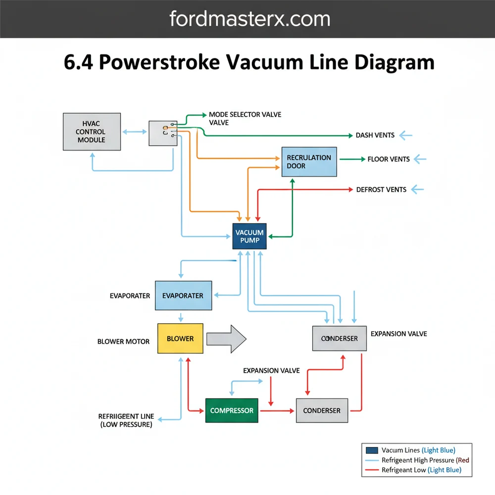
The vacuum architecture of the 6.4L Powerstroke is unique compared to its gasoline counterparts. Because the diesel engine lacks throttle-plate-induced vacuum, Ford utilizes an electric pump located on the passenger-side inner fender well. The 6.4 powerstroke vacuum line diagram visually represents a network that begins at this pump and branches out to two primary systems: the HVAC climate control actuators and the Pulse Vacuum Hublocks (PVH) for the 4×4 system.
In the diagram, you will notice a primary line exiting the electric pump and entering a vacuum reservoir tank. This tank acts as a buffer, ensuring there is enough “stored” vacuum to move heavy blend doors even when the pump isn’t running. From this reservoir, a main line passes through the firewall into the cab. Inside the dashboard, the vacuum is distributed to various actuators within the air handler. These actuators move doors that redirect air across the evaporator for cooling or the heat exchanger (heater core) for warming.
The color-coding on a standard diagram is critical. Typically, a black line represents the main vacuum supply. Red or blue lines often indicate the specific paths to the floor, vent, or defrost actuators. If your diagram shows a connection to the compressor circuit, it is usually an electrical signal rather than a vacuum line, as the compressor is engaged via an electromagnetic clutch. Understanding these distinctions prevents the common mistake of confusing refrigerant lines with vacuum hoses.
Step-by-Step Guide to Interpreting and Installing Vacuum Lines

Interpreting a vacuum schematic requires a methodical approach. Unlike electrical wiring, where a break only stops a signal, a leak in a vacuum line can affect every component “downstream” of the break. Follow these steps to master the 6.4 powerstroke vacuum line diagram and perform your own repairs.
Step 1: Locate the Source
Start your journey at the electric vacuum pump. With the ignition in the “On” position, you should hear a faint humming. If the pump runs continuously, you have a major leak. The diagram shows a single outlet hose. Ensure this hose is supple and free of dry rot. This is the “heart” of your system; if vacuum doesn’t start here, the blower motor will only push air through the defrost vents by default.
Step 2: Inspect the Vacuum Reservoir and Check Valve
The line from the pump leads directly to a plastic reservoir. The diagram will highlight a small “T” fitting or a check valve. The check valve is vital because it prevents vacuum from “bleeding” back through the pump when it is turned off. Use a hand-held vacuum pump to verify that the reservoir can hold 15-20 inches of mercury (inHg) without dropping.
Step 3: Tracing the Firewall Pass-Through
The 6.4 powerstroke vacuum line diagram shows a main line entering the cabin through a rubber grommet in the firewall. This is a common failure point where the line can become pinched or disconnected during other engine bay repairs. Ensure the line is seated deeply into the plastic coupling on the engine side of the firewall.
If you find a cracked plastic line, don’t just tape it. Cut the broken section out and use a small piece of rubber vacuum hose as a “sleeve” to bridge the gap. This creates a permanent, airtight seal.
Step 4: Mapping the Interior Air Handler
Once inside, the line connects to the climate control head unit. This is the “brain” that redirects vacuum to the evaporator (for AC) or the heat exchanger (for heat). The diagram will show multiple colored hoses exiting the control head. Each color corresponds to a specific vent position. For example, the blue line usually controls the panel vents, while the yellow line might control the floor mix.
Step 5: Testing Actuator Response
With the blower motor running on low, switch the climate settings. Watch the actuators (the small round canisters) under the dash. They should move smoothly. If an actuator doesn’t move but is receiving vacuum, the internal diaphragm is likely ruptured, requiring a component replacement.
Step 6: Integration with the Refrigerant System
While the vacuum lines do not carry refrigerant, they are intrinsically linked. When you select “Max AC,” the vacuum system closes the “Recirculation Door” in the return duct. This stops the air handler from pulling in hot outside air and instead recirculates the already cooled air from the cabin. If your truck takes a long time to cool down, check the vacuum line leading to the recirculation door actuator.
Never spray flammable cleaners or lubricants into the vacuum lines. These can degrade the rubber diaphragms inside the HVAC actuators, leading to a complete system failure that requires removing the entire dashboard to fix.
Common Issues & Troubleshooting

The most frequent complaint involving the 6.4 Powerstroke vacuum system is the “Defrost Default.” Ford designed the HVAC system to default to the defrost vents if vacuum pressure is lost; this is a safety feature to ensure the windshield can be cleared even if the system fails.
If you encounter this, use your 6.4 powerstroke vacuum line diagram to find the PVH solenoid on the passenger fender. A very common issue is a leak in the 4×4 hub seals. Because the 4WD hubs share the vacuum source, a leak at the wheels will actually kill your air conditioning’s ability to switch vents.
- ✓ Continuous Pump Operation: Indicates a leak between the pump and the reservoir.
- ✓ AC Only on Defrost: Usually a leak in the main supply line or a failed PVH solenoid.
- ✓ Hissing under Dash: Indicates a leak in the control head or a disconnected line at the air handler.
If the pump does not run at all, check the fuse box. The vacuum pump is on a dedicated circuit. If the fuse is good but the pump is silent, check the electrical connector for 12V power. If power is present, the pump motor has likely burnt out.
Tips & Best Practices for Maintenance
Maintaining your vacuum system is key to long-term reliability. The 6.4 Powerstroke operates in a high-heat environment, which can make plastic lines brittle over time.
Periodically apply a small amount of silicone-based protectant to the rubber boots and connections. This prevents the rubber from drying out and cracking due to engine bay heat.
When replacing components, always opt for OEM or high-quality heavy-duty vacuum lines. The vibrations of the 6.4L diesel engine can cause cheap, thin-walled tubing to collapse or rub through against the condenser or cooling stacks. Additionally, ensure that your return duct and cabin air filter (if equipped) are clean. A restricted return duct puts extra physical strain on the vacuum-operated doors, potentially causing the plastic hinges to snap.
Lastly, remember that the vacuum system is a “closed-loop” logic system. If you are diagnosing a cooling issue, ensure your compressor is engaging and the condenser is clear of debris. The vacuum system only controls air distribution; it cannot fix a low refrigerant charge or a failed blower motor. By combining a physical inspection with a 6.4 powerstroke vacuum line diagram, you can maintain a comfortable cab and a fully functional 4WD system for the life of your truck. Regular checks of the vacuum reservoir and the main supply lines during every oil change can help you catch small cracks before they turn into a complete loss of climate control on a long trip.
Frequently Asked Questions
Where is the vacuum pump located?
The vacuum pump on the 6.4 Powerstroke is typically found on the passenger side fender well. It is an electric pump that maintains pressure for the HVAC doors and 4WD solenoid. If it fails, your air vents will default to the defrost position regardless of the blower motor setting.
What does this vacuum diagram show?
This diagram illustrates the flow of vacuum from the pump through the reservoir tank to the HVAC control head and 4WD hubs. It helps identify how vacuum signals allow the blend doors to direct air through the evaporator or heater core to manage the cabin temperature effectively.
How many connections does the vacuum reservoir have?
The vacuum reservoir typically features two main connections: one inlet from the electric vacuum pump and one outlet that splits toward the dash controls and 4WD solenoid. Ensuring these ports are sealed is vital for the AC compressor to cycle and the system to maintain consistent refrigerant temperatures.
What are the symptoms of a bad vacuum line?
Common symptoms include air only blowing through the defrost vents, 4WD failing to engage, or a constantly running electric vacuum pump. If the vacuum cannot pull the actuator, the system cannot move air across the condenser or evaporator, resulting in poor cooling performance and limited vent control.
Can I replace vacuum lines myself?
Yes, replacing vacuum lines is a straightforward DIY task. By following the diagram, you can swap out brittle plastic lines with high-temperature silicone tubing. This repair is much cheaper than replacing the blower motor or AC compressor and often solves most climate control issues in these trucks.
What tools do I need for vacuum testing?
You will need a handheld vacuum pump with a gauge, a set of needle-nose pliers, and basic hand tools to access the dash area. A gauge is essential to verify if components like the evaporator doors or the vacuum reservoir can hold a steady vacuum without leaking over time.