6.4 Powerstroke Turbo Parts Diagram: Identification Guide
A 6.4 powerstroke turbo parts diagram details the complex sequential twin-turbo setup, identifying the high-pressure and low-pressure chargers, actuators, and oil lines. It helps mechanics troubleshoot issues signaled by a check engine light or diagnostic code while ensuring correct reassembly of the intake and exhaust housing components.
📌 Key Takeaways
- Provides a visual map of the sequential twin-turbocharger system
- Crucial for identifying the high-pressure vs. low-pressure turbo units
- Ensures fasteners meet the required factory torque spec for sealing
- Helps relate mechanical failures to specific electronic sensor readings
- Essential for DIY turbo removal, cleaning, or actuator replacement
The 6.4L Powerstroke engine is renowned for its advanced sequential twin-turbocharger system, a design that delivers impressive torque but also introduces significant mechanical complexity. For any diesel technician or DIY enthusiast, having a comprehensive 6.4 powerstroke turbo parts diagram is the foundation for successful maintenance, repair, or performance upgrades. This diagram serves as a roadmap to identifying the intricate high-pressure and low-pressure stages, oil delivery lines, and electronic sensors that dictate engine performance. By understanding these components through a visual guide, you can accurately diagnose boost leaks, replace failing actuators, and ensure your engine operates at peak efficiency. This article will break down every critical component, provide a step-by-step interpretation guide, and offer troubleshooting insights to keep your Powerstroke running strong.
Detailed Breakdown of the Sequential Turbocharger Components
The 6.4L Powerstroke utilizes a dual-turbocharged setup where two turbos work in series to minimize lag and maximize high-RPM power. A 6.4 powerstroke turbo parts diagram typically highlights the relationship between the atmospheric (low-pressure) turbo and the high-pressure VGT (Variable Geometry Turbocharger). The low-pressure turbo is the larger of the two, responsible for drawing in fresh air and providing the initial compression. This air is then fed into the smaller, high-pressure turbo, which features a VGT actuator to provide immediate boost at low speeds.
Key elements in the diagram include the turbo pedestal, which serves as the mounting base and the junction for oil and coolant flow. Unlike older diesel designs, the 6.4L requires a precise arrangement of up-pipes and down-pipes to manage the immense heat and pressure generated by the dual stages. The diagram also illustrates the VGT solenoid and actuator rod, which are controlled by the engine’s electronic brain to adjust the nozzle vanes within the high-pressure housing.
Furthermore, the diagram reveals the specific hardware required for a leak-free assembly, such as the multi-layered steel (MLS) gaskets for the up-pipes and the specialized O-rings for the oil drain tubes. Understanding the orientation of the atmospheric turbo vs. the high-pressure turbo is vital because they are physically stacked, making access to the lower unit particularly challenging without a clear visual reference. The diagram also points out the location of the EBP (Exhaust Back Pressure) sensor, which provides data used to modulate turbo performance.
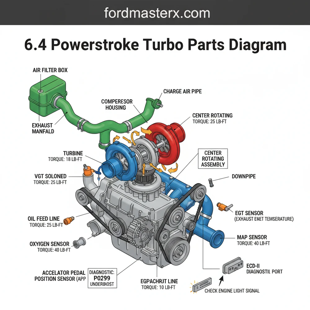
[DIAGRAM_PLACEHOLDER: A detailed technical illustration of the 6.4 Powerstroke sequential turbo system. The image shows the Large Low-Pressure Turbo at the rear, the Small High-Pressure Turbo at the front, the VGT Actuator, the Turbo Pedestal with oil feed/drain ports, the intake Y-pipe, and the mounting bolts. All components are numbered and labeled for easy identification.]
The 6.4L turbos are oil-cooled and oil-lubricated. The oil feed lines are prone to clogging if oil changes are neglected, which can lead to catastrophic bearing failure in the high-pressure turbocharger.
Interpreting the 6.4 Powerstroke Turbo Parts Diagram: A Step-by-Step Guide

Reading an automotive diagram can be daunting, but breaking it down into logical steps makes the process manageable. Whether you are performing a full replacement or just identifying a source of a “hissing” sound, follow these steps to effectively use your 6.4 powerstroke turbo parts diagram.
- ✓ Step 1: Perform Initial Diagnostics – Before diving into the hardware, use an OBD-II scanner to check for any diagnostic code stored in the ECU. A check engine light is often triggered by the VGT actuator being out of range or a mismatch in boost pressure. Common codes like P0299 (Underboost) point directly toward the components shown in the diagram.
- ✓ Step 2: Clear the Path for Inspection – To see the turbos as they appear in the diagram, you must remove the air intake assembly and potentially move the accessory belt if you need more clearance near the front of the engine. The 6.4L engine bay is notoriously tight, so identifying adjacent parts like the cooling hoses and degas bottle is the first step in physical orientation.
- ✓ Step 3: Locate the Sequential Junction – Use the diagram to identify the specific pipe connecting the low-pressure turbo to the high-pressure turbo. This is a common area for boost leaks. Inspect the clamps and silicone boots listed in the parts list for tears or loose connections.
- ✓ Step 4: Verify Oil and Coolant Flow – Identify the oil feed and return lines on the diagram. The 6.4L uses a specialized pedestal that manages these fluids. Ensure the coolant flow to the turbo housing is unobstructed, as heat soak is a major enemy of these precision-machined parts.
- ✓ Step 5: Apply Proper Torque Specs – When reassembling parts based on the diagram, always use a calibrated torque wrench. The manifold bolts and turbo mounting bolts have specific torque specs (usually between 35 and 45 ft-lbs depending on the specific fastener) to prevent exhaust leaks and warped flanges.
- ✓ Step 6: Final Verification – Once the hardware is installed according to the diagram, clear any diagnostic code from the ECU and perform a test drive. Monitor the boost levels through your OBD-II port to ensure both turbos are engaging at the correct RPM ranges.
Failure to prime the turbos with oil before the first start-up after a replacement can cause immediate bearing failure. Always fill the oil feed port before connecting the final lines.
Common Issues and Troubleshooting with the Turbo System

The 6.4L turbo system is high-performing but susceptible to specific failure modes. One of the most frequent issues is a sticking VGT actuator. This often results in a sluggish response or a “dead spot” in acceleration. By consulting the 6.4 powerstroke turbo parts diagram, you can locate the actuator rod and verify if it is moving freely or if it is bound by carbon soot accumulation.
Another common problem involves the exhaust up-pipes. These pipes lead into the turbos and are prone to cracking due to extreme heat cycles. A cracked up-pipe will cause a noticeable loss in boost, increased EGTs (Exhaust Gas Temperatures), and soot covering the back of the engine block. The diagram helps you trace the path from the exhaust manifolds to the turbo inlet to find these leaks.
If you notice a check engine light accompanied by a whining sound, you may be experiencing “compressor wheel dusting.” This happens when the air filtration system fails, allowing debris to erode the turbo blades. Using the diagram, you can identify which turbo (usually the low-pressure atmospheric unit) is affected by removing the intake boot and inspecting the wheel for physical damage or shaft play.
If you find oil in the intercooler pipes, it doesn’t always mean the turbo is blown. It could be excessive blow-by from the CCV (Crankcase Ventilation) system. Clean the pipes and re-check before replacing expensive turbo components.
Maintenance Tips and Best Practices
Maintaining the sequential turbo system on a 6.4 Powerstroke requires a proactive approach. Because the turbos share oil with the rest of the engine, the health of the timing chain and high-pressure oil pump is indirectly related to turbo longevity. Contaminated oil can wear down the timing chain guides, sending debris through the oiling system and into the turbo bearings. Always use high-quality synthetic oil and change it every 5,000 miles or sooner if you frequently tow heavy loads.
Cooling is equally critical. Ensure your coolant flow is optimal by regularly flushing the system and using the correct Ford-approved coolant. The 6.4L is sensitive to cavitation and cooling system blockage, which can lead to overheating the turbo housings and cracking the internal seals. Additionally, check the accessory belt regularly; a slipping belt can reduce water pump efficiency, leading to higher engine temperatures that negatively impact the turbochargers.
When replacing parts shown on the 6.4 powerstroke turbo parts diagram, never cut corners on gasket quality. Use only OEM or reputable high-performance aftermarket gaskets. Cheap paper or thin metal gaskets will almost certainly fail under the high-pressure environment of the 6.4L exhaust system. Finally, always keep an OBD-II monitor in the cab to watch your boost and EGT levels in real-time. Early detection of a boost deviation can save you thousands of dollars in major engine repairs.
Conclusion: Mastering the 6.4 Powerstroke Turbo System
The complexity of the 6.4L diesel engine makes a 6.4 powerstroke turbo parts diagram an indispensable tool for any owner. By understanding the relationship between the low-pressure and high-pressure turbos, and knowing how to troubleshoot components like the VGT actuator and oil feed lines, you empower yourself to handle repairs with confidence. Remember that diagnostic codes are your first line of defense, but the physical diagram is what allows you to turn those digital signals into tangible repairs. Whether you are dealing with a simple boost leak or a full turbocharger overhaul, following the proper torque specs and maintenance routines will ensure your Powerstroke remains a reliable powerhouse for years to come. Keep your cooling system healthy, your oil clean, and your diagram handy to master this sophisticated piece of engineering.
Frequently Asked Questions
Where is the turbocharger located?
The turbocharger assembly on a 6.4 Powerstroke is located at the rear of the engine valley, nestled between the cylinder heads. This top-mount position requires removing several intake components and the heat shield to access the primary and secondary units for inspection or replacement.
What does this diagram show?
This diagram displays the complete sequential turbocharger assembly, including the high-pressure (small) and low-pressure (large) turbos. It maps out the oil supply and return lines, VGT actuator, mounting pedestals, and the complex piping that connects the turbos to the intercooler and exhaust manifolds.
How many connections does the turbocharger have?
The 6.4 turbo assembly features multiple critical connections including two oil feed lines, a large oil drain, and several exhaust flange bolts. Electrically, it connects to the ECU via the VGT actuator harness and monitors boost levels through the MAP and EBP sensors for proper operation.
What are the symptoms of a bad turbo?
Common symptoms include a sudden loss of power, excessive black or blue smoke from the exhaust, and a persistent check engine light. You may also hear loud whistling or grinding noises, and an OBD-II scanner might reveal a diagnostic code related to underboost or overboost conditions.
Can I replace this turbo myself?
While possible for experienced DIYers, replacing the 6.4 Powerstroke turbo is a labor-intensive task due to the cramped engine bay and heavy components. It requires specialized tools, significant patience to reach rear bolts, and a strict adherence to every mounting torque spec to prevent future leaks.
What tools do I need for turbo service?
You will need a comprehensive metric socket set with various extensions, a high-quality torque wrench, and penetrating oil for rusted exhaust bolts. Additionally, an OBD-II diagnostic tool is necessary to clear any lingering check engine light and monitor real-time data from the ECU after the repair.