6.0 Powerstroke Fuel Line Diagram: Complete Layout Guide
The 6.0 Powerstroke fuel line diagram traces fuel from the frame-mounted HFCM to the secondary engine filter and into the cylinder heads. It illustrates the supply and return paths essential for maintaining the high pressure required for HEUI injectors. Following this map ensures proper routing and prevents air intrusion during repairs.
📌 Key Takeaways
- Visualize the complete fuel flow from the tank to the cylinder heads
- Identify the Horizontal Fuel Conditioning Module as the primary pump source
- Always adhere to the specific torque spec for fuel fittings to prevent leaks
- Use the diagram to identify potential air entry points in the return lines
- Reference the layout when troubleshooting fuel pressure or starting issues
Maintaining a diesel engine requires a deep understanding of its secondary systems, particularly the fuel delivery network. If you are a Ford Super Duty owner or a DIY mechanic, finding a clear 6.0 Powerstroke fuel line diagram is often the first step in diagnosing performance issues or performing essential upgrades. This engine, known for its HEUI (Hydraulic Electronic Unit Injection) system, relies heavily on consistent fuel pressure and volume to protect the expensive fuel injectors. In this guide, we will break down the entire fuel path—from the tank to the combustion chamber—helping you identify components, troubleshoot leaks, and understand how your fuel system interacts with the ECU and other engine sensors.
The 6.0 Powerstroke fuel system is a “dead-head” design in its stock configuration, meaning fuel enters the front of the cylinder heads and has no designated return path from the back. This makes the accuracy of your diagram interpretation vital, as any air trapped in the lines can lead to injector failure. By the end of this article, you will be equipped with the technical knowledge to navigate the fuel lines, recognize the signs of a failing lift pump, and utilize diagnostic tools to keep your engine running at peak efficiency.
The 6.0 Powerstroke requires a minimum of 45 PSI of fuel pressure at all times. Dropping below this threshold can cause the fuel to aerate, leading to “injector stiction” and permanent hardware damage.

Detailed Breakdown of the Fuel Line Diagram
A comprehensive 6.0 Powerstroke fuel line diagram illustrates a complex loop that begins at the fuel tank and travels through several filtration and regulation stages. The primary component you will see at the beginning of the diagram is the Horizontal Fuel Conditioning Module (HFCM). Located on the driver-side frame rail, this unit houses the electric lift pump, the primary fuel filter, and the water separator. The diagram shows two lines entering this unit from the tank (supply and return) and two lines exiting toward the engine.
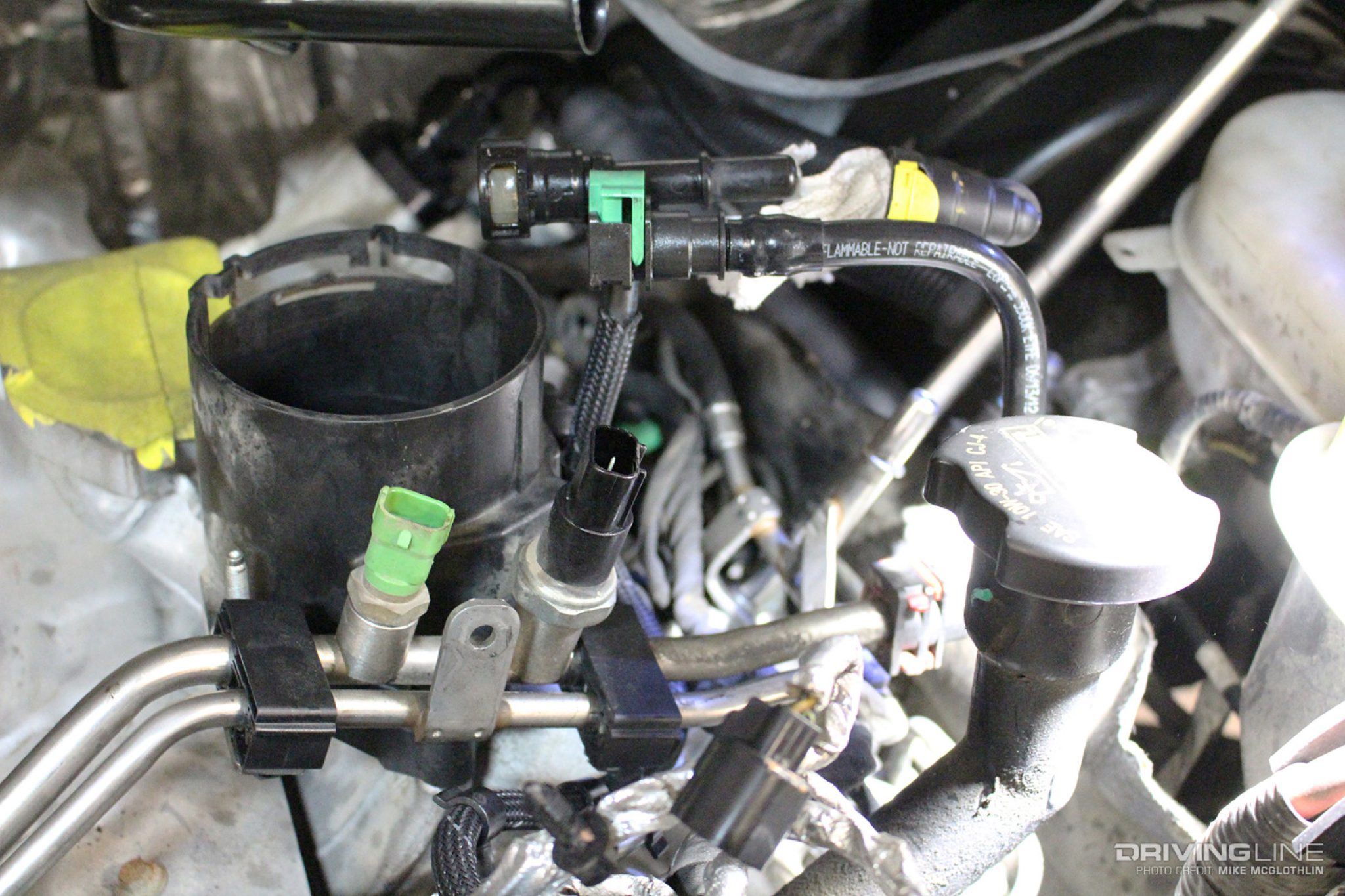
Moving from the frame rail to the engine bay, the diagram highlights the secondary fuel filter housing located on top of the engine, adjacent to the oil filter. This housing is a critical junction point. Fuel enters the secondary filter, passes through a final 4-micron pleated media, and is then routed to the cylinder heads via two braided stainless steel or steel lines. One line feeds the passenger-side head, while the other feeds the driver-side head.
A key feature often shown in detailed diagrams is the fuel pressure regulator, commonly referred to as the “Blue Spring” housing. This is located on the side of the secondary filter bowl. It contains a spring-loaded orifice that bleeds excess fuel back to the HFCM and eventually the tank. This regulator ensures the injectors see a steady pressure, preventing the “dead-head” lines from over-pressurizing or cavitating. You will also notice the fuel cooler in some diagrams, which is situated near the transmission or radiator area to lower the temperature of the returning fuel before it reaches the tank.
[DIAGRAM_PLACEHOLDER – A detailed schematic showing the Fuel Tank -> HFCM -> Secondary Filter Bowl -> Left/Right Cylinder Heads -> Return Line to Tank. Labels: HFCM, Primary Filter, Secondary Filter, Regulator Housing, Banjo Bolts, Return Line.]
Step-by-Step Guide to Reading and Navigating the System
Reading a 6.0 Powerstroke fuel line diagram is more than just looking at lines; it involves understanding the sequence of operations. Follow these steps to trace your system or perform a fuel line replacement:
1. Locate the HFCM on the Frame Rail: Start at the driver-side frame rail beneath the door. Identify the primary filter cap and the drain valve. This is the “heart” of the low-pressure fuel system. If you are experiencing a “no-start” condition, this is the first place to check for pump operation sounds.
2. Trace the Supply Lines Upward: Follow the larger diameter line from the HFCM as it travels along the frame and up the back of the engine block. It will terminate at the secondary fuel filter housing located in the engine valley.
3. Identify the Secondary Filter and Regulator: On top of the engine, find the secondary filter cap. Note the small housing on the front-facing side of the bowl. This is the regulator. Use your diagram to identify the return line that exits this regulator and heads back down to the frame rail.
4. Examine the Banjo Bolts: The fuel lines connect to the front of the cylinder heads using banjo bolts. These are hollow bolts that allow fuel to flow through them. Upgrading these to “6.4-style” banjo bolts is a common modification to increase flow, as the stock 6.0 bolts contain check valves that can be restrictive.
5. Check for Diagnostic Connections: On the secondary filter housing, there is a small brass plug (or a Schrader valve on some aftermarket caps). This is the port used to connect a mechanical pressure gauge. Using this in conjunction with an OBD-II scanner allows you to compare physical pressure with what the ECU expects.
6. Verify the Accessory Belt Clearance: Ensure that the fuel lines running near the front of the engine are properly clipped. If lines vibrate or shift, they can come into contact with the accessory belt, leading to a catastrophic fuel leak and fire hazard.
7. Inspect the Return Path: The return line takes unused fuel and air bubbles back to the HFCM. If this line is kinked, your fuel pressure will spike, potentially blowing out the seals in the secondary filter housing.
8. Final System Priming: After opening any part of the fuel system, you must prime it. Turn the key to the “On” position (do not crank) for 30 seconds. Repeat this 3-5 times. This allows the HFCM to push air through the return line and back to the tank, preventing air from reaching the injectors.
Always use a 24mm or 36mm socket for the filter caps. Using pliers or an adjustable wrench can easily crack the plastic caps, leading to air intrusion into the fuel lines.
Common Issues & Troubleshooting

When the fuel system fails, the 6.0 Powerstroke will often trigger a check engine light. However, because the 6.0 does not have a factory fuel pressure sensor that communicates with the ECU, the computer may instead throw “Misfire” or “Injector Circuit” codes. You must use an OBD-II diagnostic tool to check for a diagnostic code such as P0261 or P0264, which indicates the injectors are struggling due to poor fuel delivery.
Frequent problems include:
- ✓ HFCM Failure: The pump motor burns out, or the internal wax pellet (thermal valve) gets stuck, preventing fuel flow in cold weather.
- ✓ Air Intrusion: Cracked fuel lines or worn O-rings on the filter caps allow air to enter the system, causing a “romping” idle or hard starts.
- ✓ Regulator Spring Fatigue: The stock regulator spring weakens over time, causing fuel pressure to drop below 45 PSI under load.
If you notice a sudden drop in power or a change in the engine’s “clatter” sound, consult your fuel line diagram to check for leaks around the banjo bolts or the HFCM drain plug. If you see fuel dripping near the transmission, it is often the return line or the regulator housing O-ring.
Never attempt to tighten fuel lines while the engine is running. While the low-pressure side is only 50-65 PSI, the fuel is highly flammable, and the proximity to the accessory belt and timing chain housing poses a severe injury risk.
Tips & Best Practices for Maintenance
To ensure the longevity of your 6.0 Powerstroke fuel system, following a strict maintenance schedule is non-negotiable. Because this engine uses fuel to cool the injectors, heat is your greatest enemy.
Upgrade to the Blue Spring Kit: This is the most cost-effective insurance for your engine. The upgraded kit increases the base fuel pressure to roughly 60-65 PSI. This ensures that even under heavy towing, the injectors never run dry.
Observe Torque Specs: When replacing fuel lines or banjo bolts, always use a torque wrench. The torque spec for the fuel line banjo bolts is typically 28 lb-ft. Over-tightening can crush the copper washers, leading to a slow, weeping leak that is difficult to find later.
Monitor with OBD-II: While the ECU doesn’t monitor pressure directly, it monitors the Fuel Injection Control Module (FICM) voltage. Low fuel pressure causes the injectors to work harder, which can pull the FICM voltage down. If you see your FICM main power drop below 45 volts, check your fuel delivery system immediately.
Quality Components: Only use Motorcraft or Racor filters. The 6.0 Powerstroke secondary filter has a patented “aqua-bloc” membrane. Many aftermarket filters lack this, allowing water to pass into the injectors, which causes immediate and expensive damage.
Accessory and Belt Maintenance: Periodically check that the fuel lines are not rubbing against the accessory belt. The vibration of a diesel engine can cause plastic clips to brittle and break over time. Use high-temp zip ties or replacement looms to keep lines secured away from moving parts and the hot coolant flow pipes.
By understanding the 6.0 Powerstroke fuel line diagram and the physical layout of the system, you can perform your own diagnostics and repairs with confidence. Consistent pressure, clean filters, and leak-free lines are the keys to keeping your Powerstroke on the road for hundreds of thousands of miles.
Frequently Asked Questions
Where is the primary fuel filter located on a 6.0 Powerstroke?
The primary fuel filter is located inside the Horizontal Fuel Conditioning Module (HFCM) on the driver-side frame rail. It serves as the first stage of filtration and water separation. The secondary fuel filter is found on top of the engine, right next to the oil filter housing for easy access.
What does the 6.0 Powerstroke fuel line diagram show?
The diagram illustrates the path fuel takes from the tank, through the HFCM, up to the secondary filter housing, and into the heads. It also highlights the return path through the pressure regulator, which is vital for maintaining consistent fuel pressure and cooling the injectors during engine operation.
How many fuel line connections are on the secondary filter housing?
The secondary fuel filter housing typically features four main connections. These include the main supply line from the HFCM, two output lines that feed the left and right cylinder heads, and a return line that sends excess fuel back to the tank via the fuel pressure regulator assembly.
What are the symptoms of a bad fuel line or leak?
Symptoms include a persistent check engine light, long cranking times, or a rough idle. If the ECU detects low pressure, it may trigger a specific diagnostic code like P0087. Visible fuel puddles under the frame or a strong diesel smell while the engine is running also indicate leaks.
Can I replace the fuel lines myself on a 6.0 Powerstroke?
Yes, replacing fuel lines is a common DIY task, provided you have fuel line disconnect tools and a way to prime the system. It is critical to ensure all connections are seated perfectly and that you use an OBD-II scanner afterwards to monitor live fuel pressure for any inconsistencies.
What tools do I need for 6.0 Powerstroke fuel line repair?
You will need a set of metric sockets, a 36mm socket for the filter caps, and specialized fuel line disconnect tools. A torque wrench is essential to meet the factory torque spec on the banjo bolts. Having an OBD-II device helps verify that the system is pressurized correctly after installation.