6.0 Powerstroke Coolant Flow Diagram: Complete System Guide
The 6.0 Powerstroke coolant flow diagram illustrates fluid moving from the water pump through the engine block, oil cooler, and EGR cooler. This cooling topology acts as the primary gateway for heat regulation, ensuring each thermal subnet, including the heater core and radiator, prevents critical engine component failure and head gasket damage.
📌 Key Takeaways
- The diagram clarifies the specific path coolant takes to prevent EGR and oil cooler failure.
- Identifying the thermostat as the gateway to the radiator is critical for temperature control.
- Never open the degas bottle while the engine is hot due to high-pressure risks.
- Use this diagram to pinpoint the specific subnet where a leak or blockage is occurring.
- Refer to this map when flushing the system or replacing the water pump.
Understanding the 6.0 powerstroke coolant flow diagram is essential for any owner or mechanic looking to maintain the longevity of this specific Ford diesel engine. Because the 6.0 Liter Powerstroke relies heavily on its cooling system to regulate not just engine temperature, but also the health of the oil cooler and EGR cooler, a clear visual map is your best defense against catastrophic failure. This guide will provide a detailed look at the cooling topology, explaining how fluid travels from the water pump through various “subnets” of the engine block and back to the radiator. You will learn to identify key components and troubleshoot flow restrictions effectively.
The 6.0 Powerstroke uses a pressurized “degas” system rather than a traditional overflow tank, meaning the pressure cap on the bottle is a critical safety valve for the entire network.
Mapping the Cooling Network Topology
The 6.0 powerstroke coolant flow diagram can be viewed as a complex network topology where the water pump acts as the primary server, distributing “data” (coolant) to various hardware components. The flow begins at the front cover, where the water pump draws cooled fluid from the bottom of the radiator. From here, the fluid enters the engine block, split into two main paths. One path services the cylinder walls and heads, while the other is directed toward the critical filtration and cooling “nodes”—the oil cooler and the EGR cooler.
In this cooling architecture, the oil cooler acts as a gateway. It is a stack of plates where heat is exchanged between the engine oil and the coolant. Once the coolant passes through the oil cooler, it is directed immediately into the EGR cooler. This serial connection is a frequent point of failure; if the oil cooler “subnet” becomes clogged with casting sand or silicate fallout, the EGR cooler loses its flow, leading to localized boiling and potential internal ruptures.
The return path functions much like a network switch, directing fluid based on thermal demands. When the engine is below operating temperature, the thermostat remains closed, forcing the coolant through a bypass circuit back to the water pump. Once the thermostat (the system’s physical gateway) opens, the fluid is routed through the upper radiator hose into the radiator for heat dissipation. The degas bottle serves as the administrative hub, managing air separation and providing a point for pressure relief.
graph TD
    WP[Water Pump] --> BC[Block & Cylinder Heads]
    WP --> OC[Oil Cooler Gateway]
    OC --> EGR[EGR Cooler]
    BC --> TSTAT{Thermostat}
    EGR --> TSTAT
    TSTAT -- Closed --> BYP[Bypass Loop]
    BYP --> WP
    TSTAT -- Open --> RAD[Radiator]
    RAD --> WP
    DB[Degas Bottle] -.-> WP
    RAD -.-> DB
Step-by-Step Guide to Interpreting and Testing Flow

Tracing the 6.0 powerstroke coolant flow diagram requires a methodical approach, much like a network technician would use to ping an IP address or check a subnet mask. Follow these steps to understand and verify your system’s integrity.
- ✓ 1. Identify the Source: Locate the water pump behind the primary fan clutch. This is the starting point of all pressure in the system.
- ✓ 2. Locate the Oil Cooler Port: Find the coolant manifold on top of the engine block. This is where the “subnet” for oil cooling begins.
- ✓ 3. Trace to the EGR Cooler: Follow the small blue or orange silicone hose connecting the oil cooler outlet to the EGR cooler inlet.
- ✓ 4. Observe the Return Path: Note how the EGR cooler exit merges with the coolant coming from the cylinder heads at the thermostat housing.
- ✓ 5. Check the Degas Line: Identify the small 3/8-inch line running from the top of the radiator to the degas bottle; this removes air pockets from the network.
To perform a professional diagnostic, you will need a digital monitor capable of reading the Engine Oil Temperature (EOT) and Engine Coolant Temperature (ECT). Think of these as the diagnostic logs of your system.
Always check the “Delta” or temperature difference between the ECT and EOT. After the engine is fully warmed up and driving at 65 mph, the EOT should not be more than 15 degrees Fahrenheit higher than the ECT. A higher spread indicates a clogged oil cooler “gateway.”
Safety is paramount when working with this system. Never open the degas bottle while the engine is hot. The system operates at approximately 16 PSI, and the liquid inside can exceed 220 degrees Fahrenheit. If you are replacing components, ensure you have a vacuum refill tool to prevent “air-locking” the system, which can cause local hotspots in the cylinder heads.
Common Issues & Troubleshooting

The most frequent issue diagnosed via the 6.0 powerstroke coolant flow diagram is a “ruptured” EGR cooler. However, the diagram reveals that the EGR cooler is rarely the root cause; it is usually the victim of a clogged oil cooler. When the fine passages in the oil cooler become restricted, the downstream EGR cooler is starved of fluid, causing it to overheat and crack.
Warning signs include white smoke from the exhaust (steam), disappearing coolant without visible leaks, and high pressure in the degas bottle. You can use the “bubble test” to see if combustion gases are entering the cooling network, which indicates a failure in the head gaskets or the EGR cooler internal walls. If your diagnostic tool shows fluctuating temperatures, check the thermostat; it may be stuck in a partially open position, failing to act as a proper gateway to the radiator.
Excessive pressure in the cooling system (over 16 PSI) will vent through the degas cap. If you see white crusty residue around the cap, your system is over-pressurizing, likely due to blown head gaskets or a flash-boiling EGR cooler.
Tips & Best Practices for Cooling Longevity
To maintain a healthy 6.0 powerstroke coolant flow, you should treat the system maintenance like a network administrator treats server updates. The original Ford Gold coolant is known to drop silicates over time, which act like debris in a switch, clogging the small passages of the oil cooler. Many enthusiasts recommend switching to a Nitrite-Free Extended Life Coolant (ELC) that meets the EC-1 specification. This prevents the “sludging” that kills the cooling topology.
Another best practice is the installation of a coolant filtration system. This bypass filter acts like a firewall, capturing casting sand and suspended solids before they can reach the oil cooler. It is a low-cost insurance policy that significantly extends the life of the engine’s internal components.
Finally, ensure your fan clutch is functioning correctly. The PCM (Powertrain Control Module) controls the fan speed based on various sensor inputs. If your fan doesn’t roar when the engine gets hot, you may have a communication issue in the electronic side of the cooling network. Using a high-quality scan tool to monitor the fan’s duty cycle can help you verify that the “DHCP” of the engine—the PCM—is correctly requesting cooling when the system reaches its thermal limits.
By following this 6.0 powerstroke coolant flow diagram and maintaining the various “nodes” of the system, you can ensure your diesel engine remains reliable for hundreds of thousands of miles. Consistency in flushing the system and monitoring temperature deltas is the key to preventing the most common failures associated with this platform.
Frequently Asked Questions
Where is the oil cooler located?
The oil cooler is located deep within the engine valley, positioned beneath the oil filter housing and intake manifold. In the system topology, it acts as a critical node where heat is exchanged between the engine oil and the coolant subnet before the fluid reaches the EGR cooler.
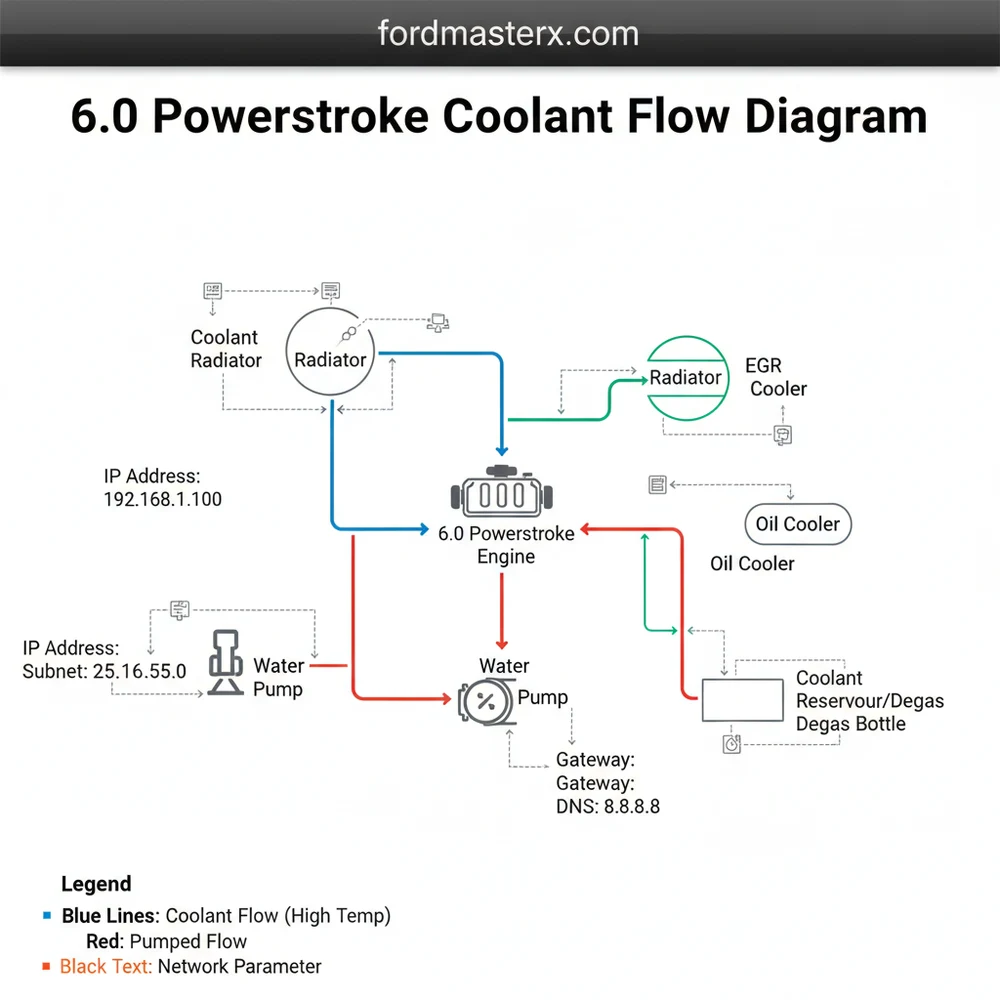
What does the 6.0 Powerstroke coolant flow diagram show?
The diagram shows the directional movement of coolant starting from the water pump, through the front cover, into the block, and then through the oil cooler and EGR cooler. It maps out the system’s DNS—the ‘Detailed Network Scheme’—of hoses and passages that keep the engine within safe limits.
How many connections does the degas bottle have?
The degas bottle typically features three main connections: a large lower hose for coolant supply, a small vent line from the radiator, and a small vent line from the intake manifold. These connections serve as the management interface for air separation and pressure regulation within the cooling network.
What are the symptoms of a bad oil cooler?
Primary symptoms include high Delta T (temperature difference) between oil and coolant, resulting in overheating or ‘goo’ in the degas bottle. If the oil cooler subnet fails, it often leads to an IP address—’Immediate Problem’—at the EGR cooler, which may rupture due to lack of coolant flow.
Can I flush the coolant system myself?
Yes, a DIY flush is feasible with basic tools and a garden hose adapter. By following the flow diagram, you can isolate specific subnets to ensure all debris is removed. However, ensure you use the correct Ford-approved ELC coolant to prevent clogging the narrow oil cooler passages.
What tools do I need for cooling system repair?
You will need a standard socket set, pliers for hose clamps, a torque wrench, and a vacuum refill kit for the best results. A digital monitor is also recommended to track the ‘IP address’ of your sensors, ensuring the gateway thermostat opens correctly during the initial startup phase.