3 Wire Ignition Coil Wiring Diagram: Easy Setup Guide
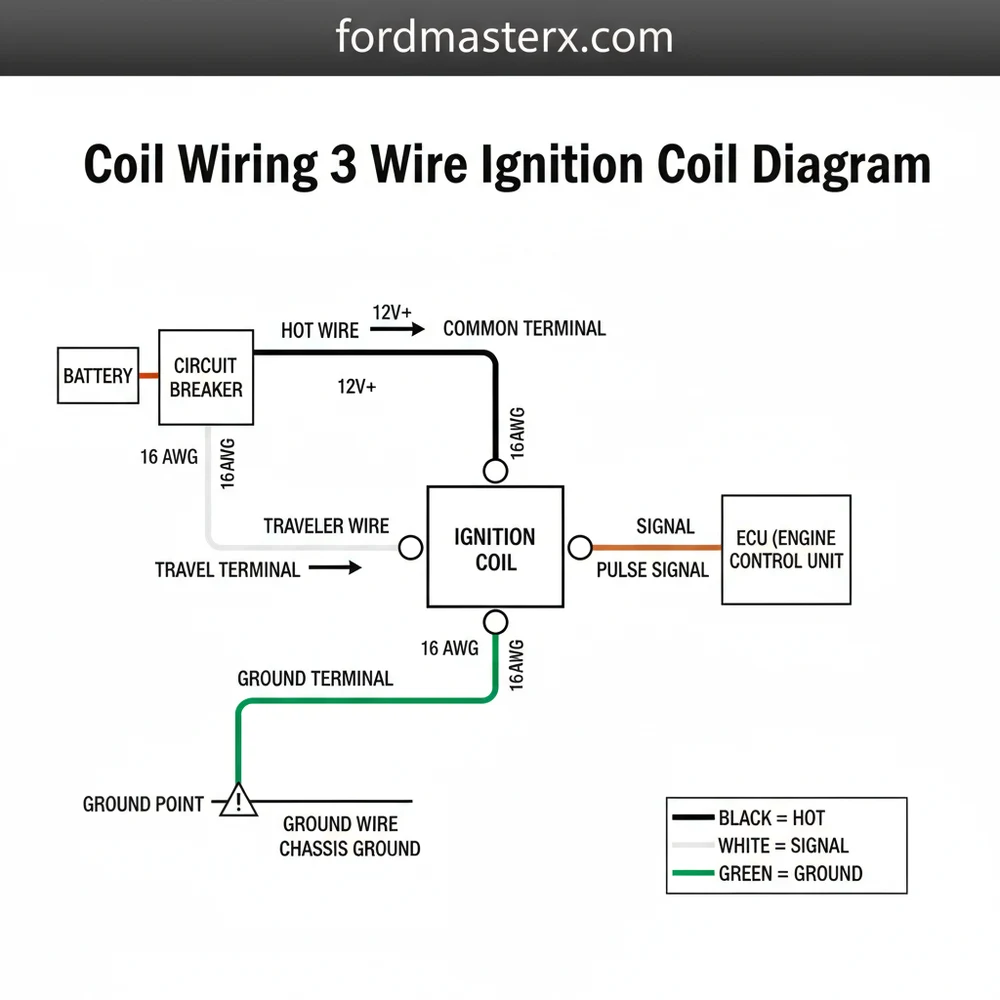
A 3 wire ignition coil wiring diagram illustrates the connections for the hot wire (12V), the ground wire, and the traveler wire used for signaling. These wires meet at the common terminal to trigger the spark. Understanding this layout ensures you maintain consistent ignition timing and prevent electrical shorts.
📌 Key Takeaways
- Map out the electrical flow from the ignition switch accurately.
- Identifying the traveler wire from the ignition module is essential.
- Proper grounding is critical for circuit completion and coil safety.
- Use a digital multimeter to check for continuity and voltage levels.
- Referencing this diagram during engine swaps or coil replacements saves time.
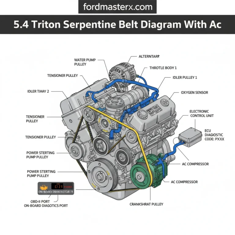
The ignition coil is the heart of an internal combustion engine’s electrical system, acting as a compact high-voltage transformer that converts low battery voltage into the thousands of volts required to bridge the gap of a spark plug. While older systems often used simple two-wire canisters, many modern small engines, motorcycles, and classic automotive electronic ignition conversions utilize a three-wire ignition coil configuration. Understanding the “coil wiring 3 wire ignition coil diagram” is essential for any DIY enthusiast looking to troubleshoot a no-spark condition, perform an engine swap, or upgrade an aging ignition system. This configuration typically integrates the primary power, the switching trigger, and a dedicated ground or tachometer output, making it slightly more complex than its predecessors but significantly more efficient.
For the home mechanic, miswiring an ignition coil isn’t just a matter of the engine not starting; it can lead to catastrophic failure of the Electronic Control Unit (ECU), burnt-out points, or a melted wiring harness. By mastering the layout of these three wires, you gain the ability to diagnose electrical gremlins and ensure your engine runs with peak timing accuracy and thermal efficiency. This guide will break down the anatomy of these coils, how to interpret their wiring diagrams, and the practical steps needed to install or repair them safely.
Main Components and Features
A three-wire ignition coil is more than just a spool of wire; it is a precisely engineered component designed to handle extreme heat and high-frequency electrical pulses. To understand the wiring diagram, you must first understand what resides inside the plastic or epoxy housing. The three wires typically correspond to the primary circuit’s entry and exit points, along with a specialized third lead.
- The Primary Winding: This consists of a relatively small number of turns of heavy-gauge copper wire. When you turn the key, battery voltage (usually 12.6V to 14.4V) flows through this winding, creating a magnetic field.
- The Secondary Winding: This is made of thousands of turns of very fine wire. When the primary circuit is suddenly interrupted (the “trigger”), the collapsing magnetic field induces a massive voltage in the secondary winding, which then travels out through the thick high-tension (HT) lead to the spark plug.
- The Connector Terminals: In a three-wire setup, these are usually labeled or color-coded. While specific manufacturers vary, the general roles are:
- Positive (+) or Terminal 15: The switched power source from the ignition relay or battery.
- Negative (-) or Terminal 1: The “Trigger” or “Signal” wire that connects to the ignition module, ECU, or contact breaker points.
- Ground/Tachometer (The 3rd Wire): Depending on the design, this third wire is either a dedicated chassis ground for the secondary circuit or a signal wire sent to the vehicle’s dashboard to display RPMs (tachometer).
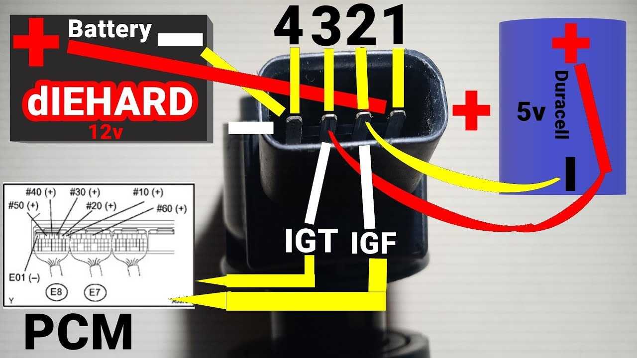
Modern three-wire coils often feature an integrated igniter. In these “smart coils,” the three wires are typically Power (12V), Ground, and a low-voltage Trigger Signal (5V or 12V) from the ECU. This eliminates the need for a separate ignition module, as the switching happens inside the coil housing itself. Knowing whether you have a “dumb” coil (requires an external switch) or a “smart” coil (switches itself) is the first step in reading any diagram correctly.
How to Use and Read a 3-Wire Diagram
Reading a wiring diagram can feel like deciphering an alien language, but it follows a logical flow from the power source to the ground. When looking at a 3-wire ignition coil diagram, follow the path of the current. Most diagrams will display the battery on one side and the engine block (ground) on the other.
Step 1: Identify the Power Lead (Positive)
On most diagrams, this wire is color-coded Red or Black with a White stripe. It connects to the “15” or “+” terminal. In a practical application, you can verify this with a multimeter. With the ignition key in the “ON” position, this wire should show roughly 12.5 volts. If the voltage is significantly lower (e.g., 9V), you may have a resistor wire in the circuit designed to protect the coil from overheating during low-RPM operation.
Step 2: Identify the Trigger Lead (Negative)
The trigger wire is the most active part of the system. On a diagram, it usually goes to a “Module,” “CDI Box,” or “Points.” Common colors include Green, Blue, or Yellow. This wire is responsible for “breaking” the ground connection. When the ground is broken, the spark occurs. On a 3-wire “smart” coil, this wire carries a low-current square wave signal from the computer rather than a direct ground load.
Step 3: Identify the Third Wire (Ground or Tach)
This is where DIYers often get confused. Look closely at the diagram symbol for this wire. If it ends in a series of three decreasing horizontal lines, it is a Chassis Ground (usually a Black wire). This provides a clean path for the secondary high-voltage circuit to complete its loop back from the spark plug. If the wire leads toward the instrument cluster, it is a Tachometer Signal. Connecting a ground wire to a tachometer input (or vice-versa) can result in a dead gauge or a blown fuse.
Standard Measurements for Testing:
When following a diagram, you should use a multimeter set to Ohms (Ω) to verify the coil matches the diagram’s specs.
- Primary Resistance: Measure between the (+) and (-) pins. Most high-energy 3-wire coils should read between 0.5 and 2.0 ohms.
- Secondary Resistance: Measure between the (+) pin and the high-tension output (where the spark plug wire goes). You should see between 6,000 and 15,000 ohms (6kΩ to 15kΩ).
Installation and Maintenance Tips
Wiring a 3-wire coil correctly is only half the battle; ensuring it lasts requires attention to environmental factors and connection quality. Ignition coils generate significant heat, and they are also sensitive to vibration.
- Heat Management: Ensure the coil is mounted in a location with adequate airflow. Many DIYers make the mistake of mounting the coil directly to the engine block for convenience. However, engine heat can shorten the lifespan of the internal windings. Use a bracket with rubber isolators if possible to reduce vibration.
- Wire Gauges: For a 12V system, the Power (+) and Ground wires should be at least 16-gauge or 14-gauge wire to handle the current draw without voltage drop. The trigger signal wire can be thinner (18-gauge) if it is a low-voltage signal for a smart coil.
- Clean Contacts: Before connecting your wires, use a small piece of sandpaper or a wire brush to clean the mounting point on the chassis. A “weak” third-wire ground is the leading cause of “weak spark” symptoms, where the engine starts but stumbles under load.
- Dielectric Grease: Apply a small amount of dielectric grease to the inside of the spark plug boot and the low-voltage connector. This prevents moisture intrusion and makes future removal much easier.
Troubleshooting Common Wiring Issues
If you have followed the 3-wire ignition coil diagram but still have no spark, or if your engine is running poorly, you need a systematic approach to troubleshooting. Most ignition problems are not caused by a “dead” coil, but rather by poor wiring or incorrect signal inputs.
1. The “No-Spark” Condition
First, check for power. With the ignition on, use a test light or multimeter on the Positive (+) wire. If there is no power, check the ignition fuse or the ignition switch. Next, check the trigger. While cranking the engine, a test light connected between the Positive (+) and the Trigger (-) should flicker. If it doesn’t flicker, your ignition module or crank position sensor (which tells the coil when to fire) is likely faulty.
2. Intermittent Misfires
This is often caused by a “leaking” high-tension lead or a loose third-wire ground. In a dark garage, run the engine and look for small blue arcs of electricity jumping from the coil to the frame. This indicates the insulation has failed. Additionally, check the resistance of the third wire. If it shows more than 0.2 ohms of resistance to the negative battery terminal, you need to clean your ground points.
3. Overheating Coil
If the coil is hot to the touch (too hot to hold) after only a few minutes of running, you may have the wrong type of coil for your system. For example, using a high-output 3-wire coil designed for an electronic ignition on an old “points” system without a ballast resistor will cause the coil to draw too much current and eventually melt internal components.
4. Tachometer Issues
If your engine runs but the tachometer stays at zero, you may have swapped the trigger wire and the tachometer wire. While they both connect to the “negative” side of the primary circuit, the tachometer lead usually has a filter or a specific resistor in-line. Refer back to your specific vehicle’s diagram to ensure the signal is being pulled from the correct terminal.
By carefully following a 3-wire ignition coil diagram and taking the time to verify each connection with a multimeter, you can ensure a reliable, high-energy spark that improves throttle response and fuel economy. Whether you are building a custom cafe racer or maintaining a vintage tractor, the principles of power, trigger, and ground remain the foundation of a healthy ignition system.
Step-by-Step Guide to Understanding the 3 Wire Ignition Coil Wiring Diagram: Easy Setup Guide
Identify the three distinct terminals on the ignition coil housing.
Locate the hot wire providing 12V DC power from the ignition switch.
Understand how the traveler wire sends the timing signal from the ECU.
Connect the ground wire to a clean chassis point or the engine block.
Verify that the neutral wire or ground path at the common terminal is secure.
Complete the installation by testing the spark output with an inline tester.
Frequently Asked Questions
Where is the ignition coil located?
The ignition coil is typically located on the engine block or cylinder head, often directly above the spark plugs in Coil-on-Plug systems. In older vehicles, it may be mounted on the firewall. Locating it allows you to trace the three wires back to the main harness or battery source.
What does this diagram show?
This diagram shows the electrical path between the battery, the ignition module, and the coil. It highlights how the hot wire provides power while the traveler wire regulates the timing. By following the schematic, you can identify which pin acts as the common terminal for grounding and signal processing.
How many connections does a 3 wire ignition coil have?
A 3 wire ignition coil has three specific electrical connections: a positive 12V feed, a ground connection, and a trigger signal wire. The trigger wire, often called the traveler wire, receives pulses from the engine control unit to determine exactly when the coil should fire the spark plug.
What are the symptoms of a bad ignition coil?
Symptoms of a failing ignition coil include engine misfiring, rough idling, a noticeable loss of power, and reduced fuel economy. You might also notice the check engine light flashing. If the common terminal or internal windings fail, the vehicle may experience hard starts or stall completely during operation.
Can I replace an ignition coil myself?
Yes, replacing an ignition coil is a straightforward DIY task that usually requires basic hand tools. By following a wiring diagram, you can easily disconnect the old unit and secure the new one. Always ensure the battery is disconnected before touching the hot wire to prevent accidental electrical shocks.
What tools do I need for coil wiring?
To wire or replace a coil, you will need a socket set for mounting bolts, a digital multimeter for testing voltage, and dielectric grease for the terminals. Wire strippers and crimpers are also helpful if you need to repair the harness or replace the connector at the common terminal.