3 Wire Distributor Wiring Diagram: Easy Setup Guide
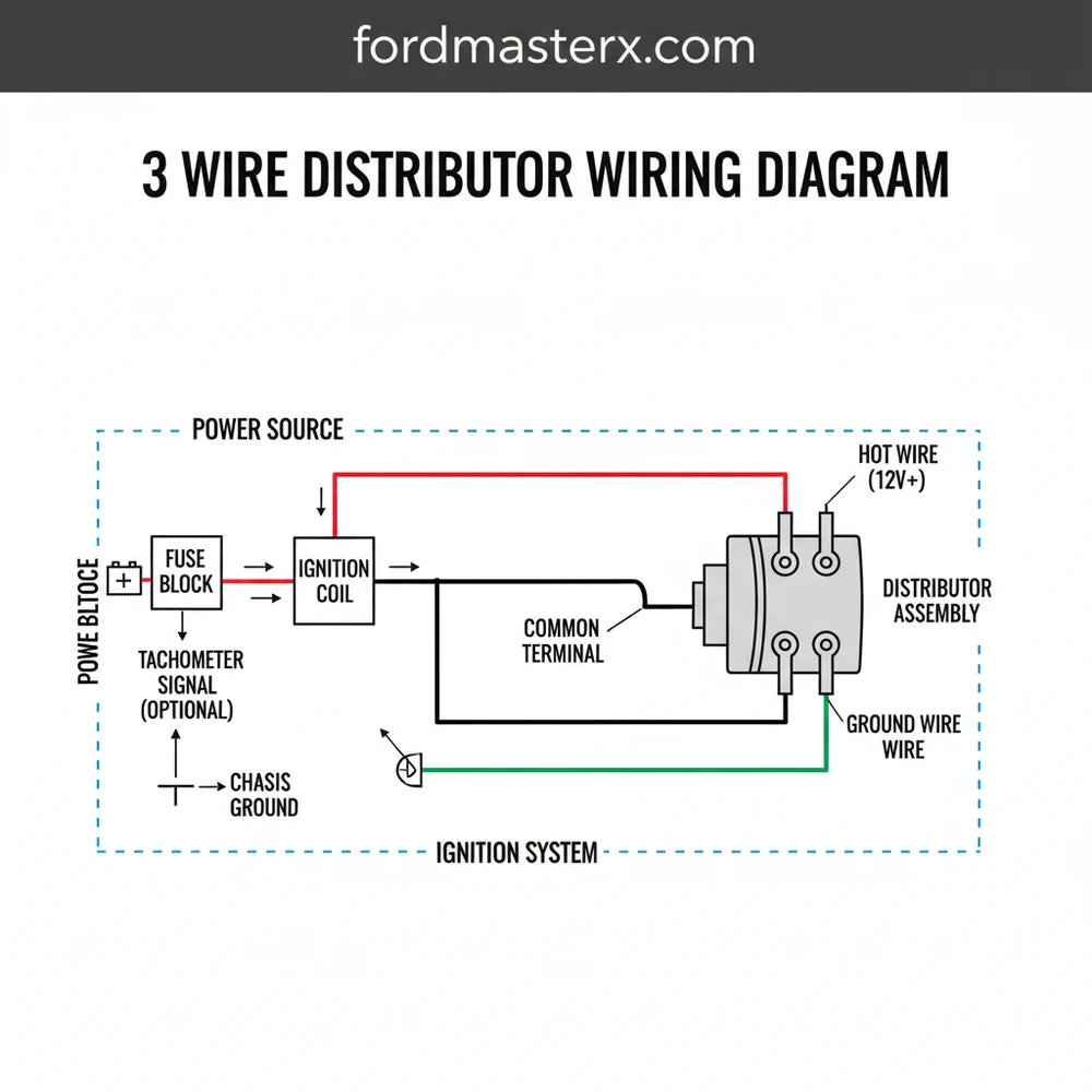
A 3 wire distributor wiring diagram illustrates the essential connections between the ignition switch, coil, and distributor. It typically includes a hot wire for 12V power, a signal traveler wire leading to the ignition coil, and a ground wire. Locating the common terminal correctly ensures the ignition module triggers the spark precisely.
📌 Key Takeaways
- Identifies the power, ground, and signal paths for electronic ignition
- Correctly mapping the common terminal prevents module burnout
- Always disconnect the battery before attempting any wiring changes
- Use a multimeter to verify the hot wire voltage before connection
- Essential for HEI conversions or replacing vintage points systems
Understanding a 3 wire distributor wiring diagram is a fundamental skill for any automotive enthusiast, DIY mechanic, or restoration specialist. When you are tasked with upgrading an old points-style ignition to a modern electronic system or simply replacing a faulty unit, the wiring configuration can often seem daunting. This guide is designed to demystify the process by providing a clear visual and descriptive roadmap of how these three essential connections function together. By the end of this article, you will be able to identify each terminal with confidence, understand the significance of wire color coding, and execute a flawless installation that ensures your engine starts reliably and runs at peak efficiency. We will cover everything from basic terminal identification to troubleshooting complex signal issues, giving you the technical edge needed for a professional-grade result.
Decoding the 3 Wire Distributor Wiring Diagram
The core of a 3 wire distributor wiring diagram lies in its simplicity, yet each of the three connections performs a critical, non-negotiable role in the ignition cycle. In a standard electronic distributor—typically utilizing a Hall Effect or optical sensor—the three wires are categorized as power, signal, and ground. While specific manufacturers may vary their color schemes, the functional logic remains consistent across most platforms. The diagram illustrates how the distributor interfaces with the ignition coil and the vehicle’s electrical system to provide the precise timing required for internal combustion.
The first wire is the hot wire, which provides the necessary 12-volt power to the internal module. This is often connected to a switched ignition source to ensure the distributor only receives power when the key is in the “On” or “Start” position. The second wire is the signal wire, often referred to as the “tach” or “trigger” lead. This wire sends a pulse to the ignition coil or the engine control unit (ECU) every time the distributor shaft rotates past a sensor point, telling the coil exactly when to fire the spark plugs. The third wire is the ground wire, which completes the circuit. Without a solid, low-resistance path back to the negative battery terminal, the sensitive electronics inside the distributor can fail or produce erratic timing.
Most 3-wire systems use a Red/Black/Green or Red/Black/White color code. Always consult the specific manufacturer’s documentation to confirm if the common terminal on your specific module follows these standard conventions before applying power.
In some high-performance or specialized applications, you might encounter terminology like the traveler wire or common terminal. While these terms are more prevalent in residential electrical circuits, they are occasionally used by technicians to describe the “loop” between the ignition switch, the distributor, and the coil. Furthermore, the physical connection points on the distributor cap or the external ignition box often feature a brass screw or high-conductivity terminal to ensure that the voltage delivery remains constant despite engine vibrations and heat expansion.
Step-by-Step Installation and Wiring Guide

Properly implementing a 3 wire distributor wiring diagram requires a methodical approach. Before you begin, ensure you have the correct gauge of wire; typically, 14-gauge or 16-gauge wire is sufficient for the low-current signal and power leads, though the main power feed should never be undersized to avoid voltage drops. Follow these steps to ensure a secure and functional connection:
- ✓ Step 1: Preparation and Safety – Disconnect the negative battery cable. This prevents accidental shorts that could blow the sensitive internal module of your new distributor. Locate a clean mounting spot for any external components and ensure the distributor is seated correctly in the engine block.
- ✓ Step 2: Identify the Hot Wire – Locate the “BATT” or “+” terminal on your ignition coil or the designated power lead from your ignition switch. This hot wire must provide a full 12 volts. If your vehicle previously used a ballast resistor for a points system, you may need to bypass it to ensure the electronic distributor receives the proper voltage.
- ✓ Step 3: Connect the Ground Wire – Connect the black wire from the distributor to a reliable engine ground or the negative battery terminal. Do not rely solely on the distributor housing’s contact with the engine block, as oil and gaskets can create resistance. A dedicated ground wire ensures the module’s longevity.
- ✓ Step 4: Route the Signal Wire – Connect the signal or trigger wire (often green or white) to the negative (-) terminal of the ignition coil. This is the common terminal for signal interruption that triggers the spark. If you are using an aftermarket ignition box, this wire will typically connect to the “Points” or “Tach Input” on that box.
- ✓ Step 5: Secure the Terminals – Use high-quality crimp connectors or solder your joints. If the distributor uses a brass screw terminal, ensure the wire is wrapped clockwise around the screw before tightening to prevent it from backing out under vibration.
- ✓ Step 6: Final Inspection and Testing – Double-check that no wires are resting against the exhaust manifold or moving parts. Reconnect the battery and use a multi-meter to verify that the voltage at the distributor matches the battery voltage when the key is on.
Never swap the hot wire and the ground wire. Most electronic distributors lack reverse-polarity protection, and even a split-second of incorrect connection can permanently destroy the internal sensors.
Common Issues & Troubleshooting
Even with a perfect 3 wire distributor wiring diagram, issues can arise during the first startup. The most frequent problem is a “no-start” condition caused by inadequate voltage. Electronic distributors are far more sensitive than old mechanical points; if your battery drops below 10.5 volts during cranking, the module may not trigger the signal wire. Use a voltmeter to check the common terminal while the engine is turning over to ensure the power remains steady.
Another common culprit is poor grounding. If the ground wire is attached to a painted surface or a rusty bolt, the circuit will be “dirty,” leading to engine misfires or intermittent stalling. Furthermore, ensure that the signal wire is kept away from high-voltage spark plug wires. The electromagnetic interference (EMI) from the plug wires can “ghost” the signal, causing the distributor to trigger at the wrong time. If you experience erratic tachometer readings or backfiring, inspect the neutral wire path (the return path to ground) and the integrity of the brass screw connections for any signs of loosening or corrosion.
Tips & Best Practices for Long-Term Reliability
To get the most out of your wiring project, consider the environment in which the wires reside. The engine bay is a harsh place with extreme heat cycles and chemical exposure. Always use automotive-grade TXL or GXL wire, as the insulation is designed to withstand these conditions without becoming brittle. When selecting your gauge, remember that a slightly thicker wire is always better than one that is too thin, especially for the ground path.
Apply a small amount of dielectric grease to the brass screw terminals and inside the wire connectors. This prevents moisture from causing oxidation, which is the primary cause of signal degradation over time.
Maintenance is also key. Every six months, perform a visual check of your wiring loom. Look for any signs of heat scorching on the hot wire or fraying near the distributor’s entry point. If you are using a traveler wire setup to an external tachometer, ensure the connection at the common terminal is tight. Quality components, such as genuine heat-shrink tubing and nylon loom, are low-cost investments that can save you from expensive roadside breakdowns. By following the 3 wire distributor wiring diagram and these best practices, you ensure that your ignition system remains the most reliable part of your vehicle’s powertrain.
In conclusion, mastering the 3 wire distributor wiring diagram allows you to take full control of your vehicle’s ignition health. By correctly identifying the hot wire, ground wire, and signal leads, and paying close attention to voltage stability and terminal integrity, you create a robust electrical foundation. Whether you are troubleshooting an existing setup or performing a fresh installation, the principles of proper gauge selection and secure connection points will guarantee a high-performance result for years to come.
Frequently Asked Questions
Where is the 3 wire distributor located?
The 3 wire distributor is typically located at the top or side of the engine block, driven by the camshaft. Its position is critical for engine timing, often found near the firewall or at the front of the engine, depending on your specific vehicle make and engine configuration.
What does a 3 wire distributor wiring diagram show?
This diagram shows the electrical path from the 12V ignition source to the distributor module and the subsequent signal sent to the coil. It highlights how the traveler wire carries the trigger signal and how the ground wire completes the circuit, ensuring the spark plugs fire in sequence.
How many connections does a 3 wire distributor have?
A 3 wire distributor has three primary electrical connections: a positive 12V ignition feed (hot wire), a ground connection for circuit completion, and a signal output wire. While it lacks a traditional AC neutral wire, the ground serves as the return path for the DC ignition circuit.
What are the symptoms of a bad 3 wire distributor?
Common symptoms include engine misfiring, difficulty starting, or unexpected stalling. If the internal module fails or the traveler wire is damaged, the coil won’t receive the signal to fire. You might also notice erratic idling or a complete lack of spark during a diagnostic test.
Can I install this 3 wire distributor myself?
Yes, installing a 3 wire distributor is a manageable DIY task for those with basic mechanical knowledge. By following a wiring diagram, you can identify the common terminal and secure the connections. However, you must be comfortable setting engine timing and using a timing light once installed.
What tools do I need for distributor wiring?
To wire a 3 wire distributor, you will need a basic socket set to mount the unit, wire strippers, and crimpers for terminal connections. A multimeter is essential to identify the hot wire and ground, while a timing light is required to finalize the engine’s ignition timing.