3 Wire Alternator Wiring Diagram: Easy Setup Guide
A 3 wire alternator wiring diagram illustrates connections for the main battery output, the sensing wire for voltage regulation, and the ignition input. The setup ensures the internal regulator accurately monitors battery voltage through a common terminal, while the heavy-gauge hot wire charges the battery and a solid ground wire completes the circuit.
📌 Key Takeaways
- Explains the relationship between the battery, ignition, and sensing wires
- Identify the ‘S’ or sense terminal for accurate charging levels
- Ensure all connections are secure and corrosion-free for safety
- Use high-quality copper wiring to prevent voltage drops
- Use this diagram when upgrading from a 1-wire unit or replacing a stock part
Understanding the intricacies of a 3 wire alternator wiring diagram is essential for any DIY enthusiast or mechanic looking to maintain or upgrade a vehicle’s charging system. While a one-wire alternator offers simplicity, the three-wire configuration remains a standard because of its superior ability to monitor voltage and maintain a steady charge across the entire electrical system. This guide provides a comprehensive breakdown of the wiring process, focusing on terminal identification, wire color coding, and the logical sequence of connections. By the end of this article, you will have the technical knowledge required to interpret a 3 wire alternator wiring diagram and execute a professional-grade installation that ensures your battery remains charged and your electronics function reliably.
Understanding the 3 Wire Alternator Diagram Components
The 3 wire alternator wiring diagram identifies three primary connection points that differ in function and wire thickness. Unlike a simplified one-wire setup, this system utilizes a remote sensing feature to account for voltage drops across the harness. The three wires involved are generally categorized as the main battery output, the voltage sensing wire, and the ignition/exciter wire.
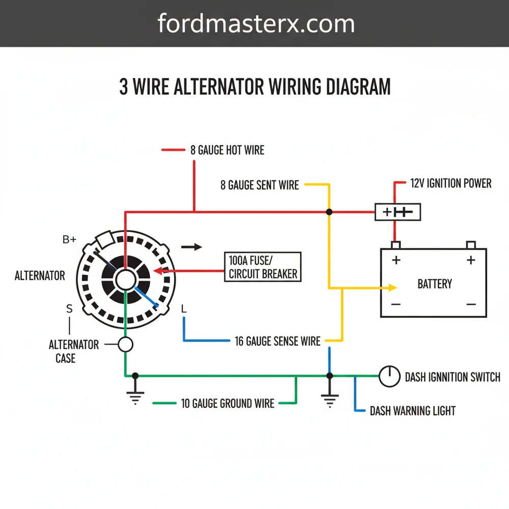
The primary terminal is known as the B+ terminal, typically represented by a large brass screw or stud on the back of the alternator. This terminal handles the heavy current and connects directly to the battery or the starter solenoid. In our diagram, this is the “hot wire” of the system, carrying the bulk of the amperage produced. The second wire is the “Sense” wire, which connects to Terminal 2 on most standard plugs. This wire monitors the actual voltage at the distribution point, ensuring the internal regulator knows exactly how much power to produce. The third wire is the “Exciter” wire, connecting to Terminal 1. This wire receives a signal from the ignition switch to “turn on” the alternator’s internal regulator when the vehicle starts.
[DIAGRAM_PLACEHOLDER: 3 Wire Alternator Wiring Diagram showing B+ Terminal to Battery, Terminal 1 to Ignition/Warning Light, and Terminal 2 to Main Power Junction Box]
Color coding is a vital aspect of reading the 3 wire alternator wiring diagram. While colors can vary by manufacturer, the main output wire is almost always a thick red wire. The sense wire is often red or white, and the exciter wire is frequently brown or white with a stripe. In this system, the alternator case itself usually serves as the ground wire connection, though a dedicated ground strap is often added for better conductivity.
In a 3 wire setup, Terminal 1 (Exciter) usually runs through a dash warning light. If the bulb burns out, the alternator may fail to charge because the circuit remains open, preventing the regulator from exciting the magnetic field.
Step-by-Step Installation and Wiring Guide

Following a 3 wire alternator wiring diagram requires a methodical approach to ensure safety and functionality. Before beginning, ensure you have a high-quality multimeter, wire crimpers, heat-shrink tubing, and various sizes of ring terminals.
Step 1: Safety and Preparation
Always begin by disconnecting the negative battery cable. This prevents accidental shorts while you are working with the hot wire connections on the alternator. Ensure the engine is cool and you have clear access to the alternator mounting bracket.
Step 2: Identifying the Terminals
Examine the back of your alternator. You will see a large threaded post (the B+ terminal) and a plastic plug with two smaller pins. These pins are usually labeled “1” and “2” or “L” and “F/S.” Referring back to your 3 wire alternator wiring diagram, identify which pin is the exciter and which is the sense terminal.
Step 3: Connecting the Main Output (B+ Wire)
This wire must be a heavy gauge to handle the high amperage. Typically, a 6-gauge or 8-gauge wire is used. Crimp a ring terminal onto the wire and secure it to the brass screw on the alternator. The other end of this wire should go directly to the positive terminal of the battery or the common terminal on the starter solenoid. Ensure this connection is tight, as a loose nut can cause arcing and heat damage.
Step 4: Wiring the Voltage Sense (Terminal 2)
The sense wire tells the alternator how much voltage is present at the main power distribution block. Do not jump this wire directly to the B+ stud on the back of the alternator; doing so defeats the purpose of the 3-wire system. Instead, run a 14-gauge wire from Terminal 2 to the main junction box or the point where the most electrical load is consumed. This ensures the alternator compensates for any voltage drop in the vehicle’s main harness.
Step 5: Wiring the Exciter/Lamp (Terminal 1)
Connect Terminal 1 to a switched ignition source. This wire acts as the “traveler wire” for the charging signal, moving from the ignition switch to the alternator. For the best results, this wire should run through a 12V incandescent bulb on your dashboard (the “ALT” or “CHG” light). When you turn the key to “On,” the light should glow; once the engine starts and the alternator begins producing current, the light should turn off. If you do not wish to use a light, you must install a resistor in this line to protect the regulator.
Never disconnect the battery while the engine is running to “test” the alternator. This can create a massive voltage spike that can destroy the internal diodes and fry sensitive electronic components like the ECU.
Step 6: Establishing a Solid Ground
While most alternators ground through the mounting bracket, paint and rust can interfere with the connection. It is highly recommended to run a dedicated ground wire (the same gauge as your B+ wire) from the alternator case directly to the engine block or the vehicle frame. This completes the circuit back to the neutral wire or negative terminal of the battery.
Step 7: Final Inspection and Testing
Check all connections against your 3 wire alternator wiring diagram. Ensure no wires are touching the exhaust manifold or moving parts like the fan belt. Reconnect the battery. Start the engine and use a multimeter to check the voltage at the battery terminals. A healthy system should read between 13.8 and 14.4 volts.
- ✓ Multimeter for voltage testing
- ✓ Heavy gauge wire (6-8 AWG) for B+ terminal
- ✓ 14-gauge wire for sense and exciter circuits
- ✓ Crimping tool and quality ring terminals
- ✓ Heat-shrink tubing for insulation
Common Issues and Troubleshooting

Even with a perfect 3 wire alternator wiring diagram, issues can arise. One common problem is the “no charge” condition. This is often caused by a blown bulb in the dash or a broken exciter wire. If the regulator doesn’t receive that initial 12V signal, it won’t start the charging process. You can troubleshoot this by checking for voltage at Terminal 1 with the key in the “On” position.
Another frequent issue is overcharging or undercharging, which is usually related to the sense wire at Terminal 2. If this wire is disconnected, the alternator may default to a high-output mode or fail to output enough voltage to maintain the battery under load. Always ensure the brass screw on the B+ terminal is free of corrosion, as resistance here creates heat and drops the available voltage.
If your dash light stays dimly lit after the engine starts, check your ground wire connections. High resistance in the ground path often causes a voltage differential that makes the light glow even when the system is charging.
Best Practices for Alternator Maintenance
To ensure the longevity of your charging system, maintenance should be a priority. Periodically check the tension of the alternator belt. A slipping belt won’t turn the pulley fast enough to reach the required voltage, regardless of how well the wiring is installed. Use a high-quality wire with a high temperature rating, especially for the hot wire running near the engine block.
When selecting components, avoid the cheapest “no-name” alternators. High-quality units use better diodes and more robust regulators that can withstand the heat of a crowded engine bay. Additionally, ensure that your wire gauge is appropriate for the amperage of your alternator. If you upgrade from a 60-amp to a 100-amp alternator, you must also upgrade the gauge of the B+ output wire to prevent it from overheating.
Finally, keep the connections clean. Use a dab of dielectric grease on the plug terminals to prevent moisture from causing corrosion. Following the 3 wire alternator wiring diagram correctly is the first step, but keeping those connections clean and tight is what ensures years of reliable service.
By meticulously following the details in a 3 wire alternator wiring diagram, you can solve most automotive charging problems yourself. Whether you are dealing with a classic car restoration or a modern engine swap, understanding the relationship between the exciter, sense, and output wires is the key to electrical success. Always double-check your terminal connections and ensure your ground paths are as short and clean as possible to get the best performance out of your charging system.
Frequently Asked Questions
Where is the 3 wire alternator located?
The 3 wire alternator is typically mounted on the front of the engine, driven by the serpentine or V-belt. It is positioned near the battery to minimize the length of the main hot wire, though specific mounting brackets vary by vehicle make and model for optimal cooling airflow.
What does a 3 wire alternator wiring diagram show?
This diagram shows how the alternator connects to the battery, ignition switch, and voltage sensor. It details the flow of electricity from the common terminal through the hot wire to charge the battery while utilizing a neutral wire or ground wire to establish a complete electrical loop.
How many wires does this alternator have?
A 3 wire alternator features three primary connections: the large battery output stud (B+), the voltage sensing terminal (S), and the ignition excitation terminal (L/I). Unlike simpler models, these extra wires allow for remote voltage sensing, ensuring the battery receives a precise charge regardless of electrical load.
What are the symptoms of a bad 3 wire alternator?
Symptoms of a bad alternator include dimming headlights, a dead battery, or a dashboard warning light. If the sense wire or traveler wire is damaged, the alternator may overcharge or undercharge the system, potentially damaging the battery or causing sensitive electronics to fail intermittently.
Can I install this 3 wire alternator myself?
Yes, you can install a 3 wire alternator yourself with basic hand tools. Most systems are straightforward, requiring you to connect the hot wire to the battery and the sense/ignition wires to the harness. Always disconnect the battery ground wire first to prevent short circuits during installation.
What tools do I need for this wiring task?
You will need a socket set, wire strippers, and a crimping tool for terminal connectors. A multimeter is essential for testing voltage at the common terminal and battery. Ensure you have high-grade electrical tape or heat shrink tubing to protect the new wiring from heat and vibration.