2 Wire Ignition Coil Diagram: Easy Setup Guide
A 2 wire ignition coil diagram illustrates the connection between the hot wire from the battery and the common terminal on the coil. By utilizing a ground wire or switching signal, the coil generates high voltage. Understanding this layout ensures you correctly route the traveler wire for consistent ignition timing and performance.
📌 Key Takeaways
- Identifies the primary path for current to enter the coil
- The common terminal is the critical link for the switching signal
- Proper grounding is essential for preventing electrical interference
- Always check wire insulation for cracks to avoid voltage leaks
- Ideal for troubleshooting older point-style or simple electronic ignitions
When you are troubleshooting a misfiring engine or performing a custom build, understanding a 2 wire ignition coil diagram is the first step toward a successful repair. Many DIY enthusiasts find themselves staring at a cylindrical coil or a small engine module, wondering which terminal receives power and which one triggers the spark. This article provides a comprehensive breakdown of the wiring sequence, terminal identification, and the electrical principles that make these components function. By following this guide, you will learn how to properly route your wires, choose the correct gauge for your application, and ensure your ignition system provides a consistent, high-intensity spark every time you turn the key.
The primary function of a 2 wire ignition coil is to act as a transformer, converting low battery voltage into the thousands of volts required to jump the spark plug gap. In a standard 2 wire ignition coil diagram, you will observe two low-voltage input terminals on the top or side of the coil, along with one large central tower for the high-tension spark plug wire. The two terminals are typically labeled as positive (+) and negative (-). The positive terminal is the hot wire connection, which receives a steady 12-volt feed from the ignition switch or battery. The negative terminal, often referred to as the common terminal in certain electrical contexts, connects to the triggering mechanism, such as contact points or an ignition module.
Depending on the manufacturer, these terminals may use different hardware. Some use a brass screw for the connection point to ensure high conductivity and corrosion resistance. The internal diagram of the coil shows two sets of copper windings: the primary winding (fewer turns of thicker wire) and the secondary winding (thousands of turns of very fine wire). When the ground circuit is broken by the ignition trigger, the magnetic field in the primary winding collapses, inducing a massive voltage spike in the secondary winding. While wire colors can vary, the most common standard uses a red or pink wire for the positive feed and a black, green, or blue wire for the negative trigger wire.
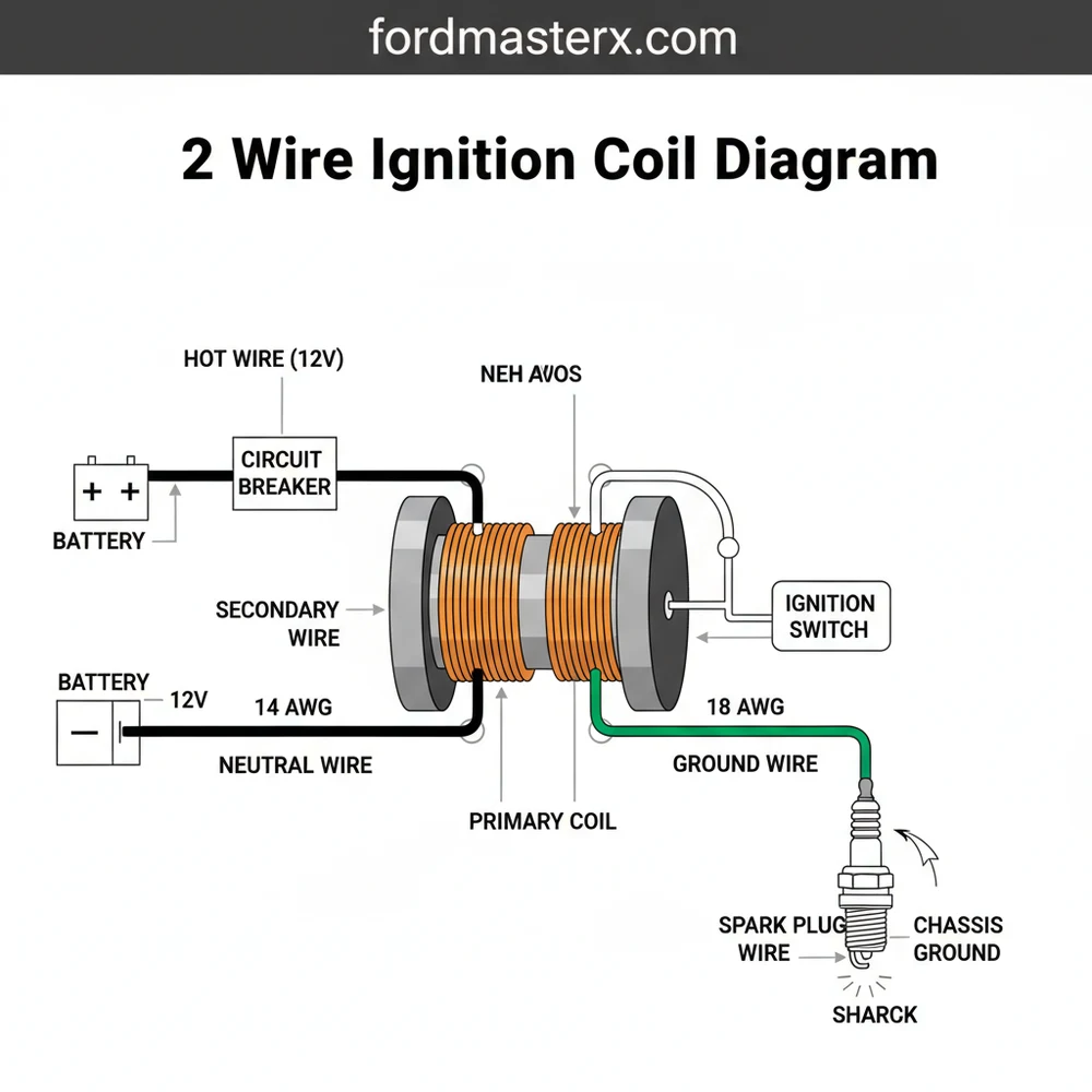
[DIAGRAM_PLACEHOLDER: A detailed 2 wire ignition coil wiring diagram showing the battery connected to an ignition switch, leading to the (+) terminal of the coil. The (-) terminal connects to a distributor or ignition module. A central high-tension lead goes to a spark plug. Labels include Hot Wire, Common Terminal, Ground Wire, and Brass Screw terminals.]
To interpret the 2 wire ignition coil diagram and perform an installation, you must understand the flow of electricity through the system. Follow these steps to ensure a safe and effective wiring process:
- ✓ Identify the Terminals: Look closely at the coil housing. Most will have a (+) and (-) stamped into the plastic or metal near the brass screw terminals. If the markings are missing, the positive terminal is usually the one connected to the ignition source.
- ✓ Check the Wire Gauge: Use the appropriate wire gauge for the primary circuit. For most automotive and small engine applications, 16-gauge or 14-gauge wire is sufficient to handle the primary current without overheating or causing a voltage drop.
- ✓ Connect the Hot Wire: Run a wire from your 12V power source (after the ignition switch) to the positive (+) terminal. This provides the “hot” potential needed to energize the coil when the vehicle is in the “on” or “start” position.
- ✓ Wire the Trigger Mechanism: Connect the negative (-) terminal to your distributor or electronic ignition module. This wire acts as a traveler wire, carrying the signal that tells the coil when to fire by opening and closing the path to the ground.
- ✓ Establish a Solid Ground: Ensure that the ignition module or the distributor housing is properly grounded to the engine block or chassis. Without a dedicated ground wire path, the circuit cannot complete, and the magnetic field will not collapse to produce a spark.
- ✓ Install the Secondary Lead: Insert the high-tension spark plug wire into the center tower of the coil. Ensure the boot is seated firmly to prevent voltage leaks or “arcing” to nearby metal components.
- ✓ Verify Resistance: Use a multimeter to check the primary and secondary resistance. This confirms that your wiring and the coil itself are within the manufacturer’s specified range before you attempt to start the engine.
In a DC ignition system, the coil does not use a neutral wire like a household AC outlet. Instead, the ground wire serves as the return path for the primary current. Always ensure the mounting bracket of the coil is clean and free of rust, as some coils use their outer shell as a secondary ground point.
When performing this installation, safety is paramount. High voltage can be dangerous even at low amperage. Always disconnect the battery before making changes to the wiring. Ensure all connections are tight; loose wires at the brass screw can create heat, which increases electrical resistance and eventually leads to coil failure.
Never touch the ignition coil or spark plug wires while the engine is cranking or running. The secondary voltage can reach 30,000 to 50,000 volts, which can deliver a painful and potentially dangerous electric shock.
Even with a perfect 2 wire ignition coil diagram, issues can arise due to component wear or environmental factors. One of the most common problems is reverse polarity. If the positive and negative wires are swapped, the spark will jump from the ground electrode to the center electrode of the spark plug, rather than the other way around. This requires about 40% more voltage to fire, leading to a weak spark and high-speed misfires.
Another frequent issue is a “dead” coil caused by excessive heat. If the coil is mounted too close to the exhaust manifold without a heat shield, the internal insulation can melt. You can diagnose this by using the diagram to identify the terminal points and testing the primary resistance with a multimeter. If the resistance is “infinite” or “zero,” the internal windings are broken or shorted. Look for signs of carbon tracking—thin, burnt lines on the outside of the coil—which indicate that the high voltage is leaking to the ground wire before it reaches the spark plug. If troubleshooting does not yield results or if you notice smoke coming from the unit, seek professional help immediately to avoid damaging your ignition module.
To get the most out of your ignition system, follow these pro tips for maintenance and installation. First, always use dielectric grease inside the spark plug boot and on the secondary tower. This prevents moisture from entering the connection and stops the boot from “welding” itself to the coil over time due to heat.
If you are using an older vehicle with points, ensure you have a ballast resistor in the circuit if the 2 wire ignition coil diagram calls for it. Some coils are designed for 6-9 volts for continuous running, and feeding them a full 12 volts constantly will cause them to overheat and fail within minutes.
When it comes to wire selection, quality matters. Choose a high-quality traveler wire with high-temperature insulation for the connection between the coil and the distributor. Standard primary wire may become brittle and crack when exposed to engine bay temperatures. For the secondary circuit, ensure your spark plug wires have a high-resistance core if you are using electronic fuel injection, as this prevents electromagnetic interference (EMI) from disrupting your vehicle’s computer. Finally, check your brass screw terminals periodically for oxidation. A quick cleaning with a wire brush can restore the voltage flow and prevent mysterious intermittent stalling issues.
By carefully following the 2 wire ignition coil diagram and adhering to the wiring steps outlined above, you can ensure your engine runs smoothly and efficiently. Proper identification of the hot wire and the common terminal is the foundation of a reliable ignition system, allowing your vehicle or equipment to perform at its peak potential. Whether you are performing a simple repair or a complete engine overhaul, a clear understanding of these electrical connections is an invaluable skill for any DIY mechanic.
Step-by-Step Guide to Understanding the 2 Wire Ignition Coil Diagram: Easy Setup Guide
Identify the primary terminals on the coil, usually labeled with positive and negative signs.
Locate the hot wire coming from the ignition switch to provide the 12-volt power source.
Understand how the traveler wire links the coil to the ignition points or electronic module.
Connect the common terminal to the switching lead to ensure the circuit can be broken to trigger a spark.
Verify that the ground wire is securely fastened to a clean, unpainted metal surface on the engine.
Complete the installation by attaching the thick high-tension wire to the spark plug or distributor cap.
Frequently Asked Questions
Where is the ignition coil located?
The ignition coil is typically located on the engine block, near the distributor, or directly atop the spark plugs in newer vehicles. In a 2-wire setup, it is often mounted to the firewall or the cylinder head to provide a stable mounting point and heat dissipation.
What does a 2 wire ignition coil diagram show?
This diagram visualizes the flow of electricity from the ignition switch through the hot wire to the coil’s primary winding. It also details how the traveler wire connects to the ignition module or points to create the pulse required to fire the spark plugs effectively.
How many connections does a 2 wire ignition coil have?
A 2-wire ignition coil features two low-voltage primary terminals and one high-voltage secondary output. One terminal receives power while the other connects to the switching mechanism. Though it lacks a dedicated neutral wire, the circuit completes through the ground wire attached to the vehicle’s metal chassis.
What are the symptoms of a bad ignition coil?
Common symptoms include engine misfires, rough idling, a noticeable loss of power, and poor fuel economy. You might also experience difficulty starting the engine or see a check engine light. In extreme cases, a failing coil can cause the vehicle to stall unexpectedly during operation.
Can I install this ignition coil myself?
Yes, installing a 2-wire ignition coil is a straightforward DIY task. It requires only basic hand tools and a clear understanding of the wiring diagram. By ensuring the common terminal and hot wire are correctly placed, most enthusiasts can complete the replacement in under thirty minutes.
What tools do I need for this task?
You will need a standard socket set or wrenches to remove mounting bolts, a multimeter to test for continuity, and wire strippers if you are repairing the harness. Using dielectric grease on the high-tension lead and ensuring a clean ground wire connection is also highly recommended.