2 Wire Alternator Wiring Diagram: Easy Setup Guide
A 2 wire alternator wiring diagram shows how to connect the main battery hot wire to the common terminal and the ignition excite wire to the regulator plug. This configuration relies on a solid ground wire through the engine block to complete the circuit, ensuring the internal regulator maintains stable voltage output.
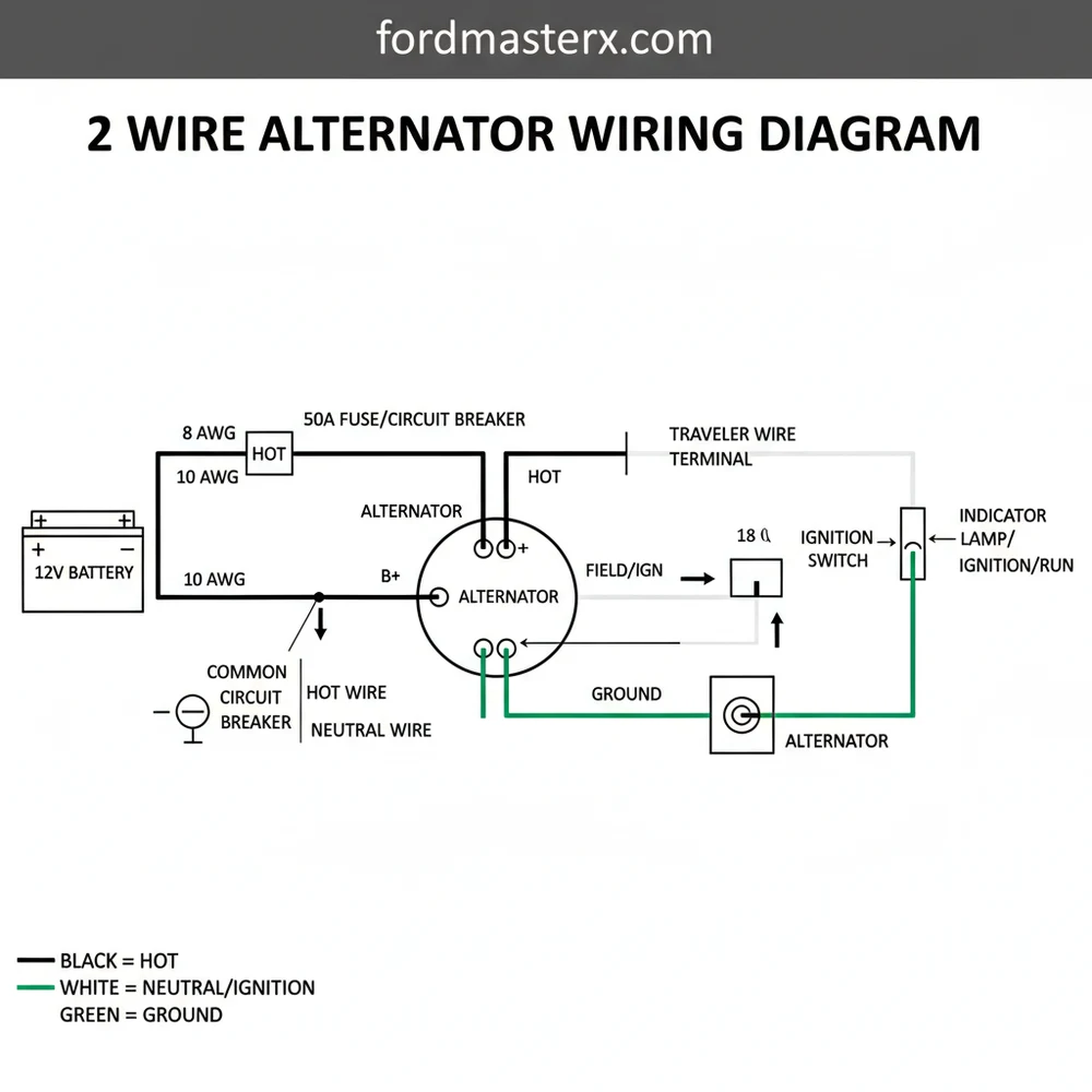
📌 Key Takeaways
- The diagram identifies the essential B+ and excitation connections.
- The B+ post serves as the primary common terminal for power output.
- A secure ground wire is mandatory for the internal regulator to function.
- The traveler wire from the ignition triggers the charging process.
- Use this diagram when converting from older external regulator systems.
This comprehensive guide explains the 2 wire alternator wiring diagram in detail. Understanding this diagram is essential for proper implementation and troubleshooting.
Step-by-Step Guide to Understanding the 2 Wire Alternator Wiring Diagram: Easy Setup Guide
Identify the B+ output stud on the back of the alternator, which acts as the common terminal for the charging circuit.
Locate the excitation pin on the regulator plug where the traveler wire from the ignition switch will be connected.
Understand how the alternator housing functions as the ground wire, ensuring the mounting bracket provides a clean path to the frame.
Connect the heavy-duty hot wire from the battery positive terminal to the B+ post, ensuring the connection is tight and insulated.
Verify that the neutral wire equivalent, or the battery’s negative cable, is securely grounded to the engine block to complete the DC loop.
Complete the installation by plugging in the excitation connector and testing the system with a multimeter to ensure the alternator is producing voltage.
Frequently Asked Questions
What is 2 wire alternator wiring diagram?
A 2 wire alternator wiring diagram is a schematic that illustrates the electrical connections for an internally regulated alternator. It highlights the main hot wire path to the battery and the ignition-switched traveler wire. This diagram simplifies the charging system by showing how the alternator interacts with the vehicle’s primary power distribution.
How do you read 2 wire alternator wiring diagram?
To read the diagram, start by locating the alternator symbol and identifying the two main terminals. One path represents the heavy-gauge hot wire going to the common terminal, while the other shows the thinner excitation wire. Symbols for the battery, ignition switch, and ground wire indicate where each connection terminates safely.
What are the parts of 2 wire alternator?
The main parts include the B+ output stud, the excitation plug, and the internal voltage regulator. Within the diagram, you will see the hot wire for power delivery and the traveler wire for system activation. The housing itself serves as the connection point for the ground wire to the engine block.
Why is common terminal important?
The common terminal on the alternator is the primary exit point for the generated current. It connects directly to the battery’s hot wire to provide a charging path. Without a secure and clean connection at this terminal, the vehicle’s electrical system will suffer from low voltage and eventual battery drainage.
What is the difference between 2 wire and 3 wire?
The 2 wire setup eliminates the separate remote voltage sensing wire found in 3 wire systems. In a 2 wire configuration, the traveler wire handles excitation while the unit senses voltage internally. Unlike AC circuits that utilize a neutral wire, both DC setups rely on a chassis ground wire to complete the circuit.
How do I use 2 wire alternator wiring diagram?
Use the diagram to verify your wiring during a replacement or upgrade. Check that the hot wire is fused and connected to the common terminal. Then, trace the traveler wire back to the ignition source to ensure the alternator receives the ‘turn-on’ signal required to start charging the battery.