Where is the Radiator Cap? Location & Safety Guide in 2026
The automotive cooling system represents a highly calibrated thermal management network, relying on precise pressurization to prevent catastrophic engine failure. At the forefront of this pressurization is a seemingly simple component that dictates the system’s maximum thermal capacity. Locating this component, however, has become increasingly complex as modern automotive architecture shifts from traditional front-mounted radiators to remote pressurized expansion tanks.
For technicians and vehicle owners alike, identifying where the radiator cap is located requires an understanding of the specific cooling system architecture utilized within the engine bay. This analysis explores the exact locations, mechanical differences, and thermodynamic principles governing radiator caps, with a specialized focus on Ford vehicle platforms.
System Architecture: Identifying the Radiator Cap Location
To pinpoint the exact location of the cooling system’s pressure threshold, one must first identify whether the vehicle utilizes an “open” overflow system or a “closed” pressurized expansion system.
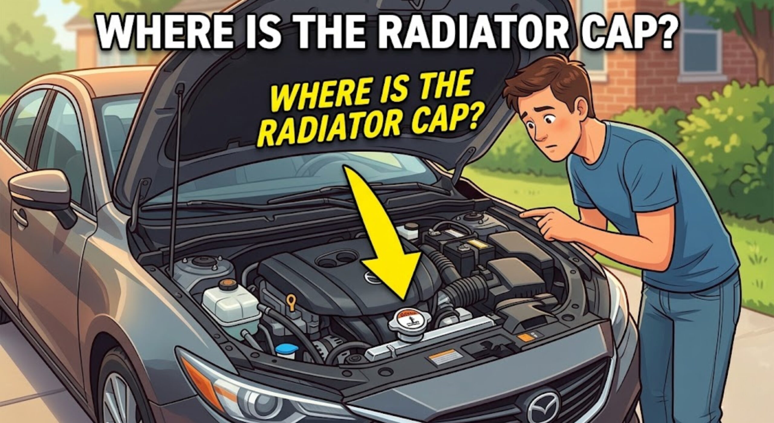
On traditional vehicles manufactured prior to the early 2000s, the radiator cap is situated directly on top of the radiator itself. Upon opening the hood, the radiator is typically mounted at the very front of the engine bay, directly behind the front grille. The cap seals the radiator filler neck and features a metallic housing with a distinct, spring-loaded pressure-release valve and winged grips for easy removal.
Conversely, modern automotive engineering has largely eliminated the traditional radiator cap from the radiator core. Due to aerodynamic hood designs and complex engine packaging, the fill point has been relocated. In these contemporary configurations, the cap is located on the highest point of a translucent plastic coolant reservoir, known industrially as a “surge tank” or “degas bottle”.
This pressurized reservoir is generally mounted on the passenger or driver side of the engine bay, near the firewall or strut tower, and utilizes a heavy-duty, threaded plastic cap with an internal relief valve.
Ford Model-Specific Locator Guide
As cooling systems became more advanced, manufacturers like Ford moved the fill point away from the radiator to utilize sealed, pressurized plastic tanks that are actively integrated into the cooling circuit. Finding the exact fill point can be challenging depending on the generation and engine displacement.
The Ford F-150, spanning the 12th through 14th generations (2009 to the present), completely lacks a traditional cap on the radiator. The cooling system is accessed exclusively via the degas bottle. On the popular 3.5L EcoBoost and 5.0L Coyote platforms, this large, spherical translucent tank is located at the front center-left of the engine bay, positioned securely above the fan shroud. The reservoir features clearly marked MIN and MAX fill lines molded directly into the plastic, allowing for visual fluid inspections without removing the cap.
On the 5th and 6th generation Ford Explorer (2011 through 2025), the pressurized coolant reservoir is mounted prominently on the passenger side of the engine bay, positioned tightly against the front fender and strut tower. The cap is a large, threaded plastic component that must ratchet securely upon installation to ensure the system seals properly.
Ford Mustang platforms (including S197, S550, and S650 generations) also utilize a passenger-side mounted degas bottle. On the 2015 through 2024 models, the reservoir sits directly behind the passenger headlight housing. Drivers must exercise caution during maintenance, as these specific plastic tanks are prone to hairline cracks along the factory seams, which can cause subtle pressure leaks over time.
Front-wheel-drive biased platforms, such as the Ford Focus, Escape, and Edge, package the degas tank tightly against the passenger side firewall or inner fender due to transverse engine layouts. Certain Focus models have notoriously brittle caps that can separate upon removal. When the plastic degrades, the outer shell twists off while the internal spring and valve remain stuck in the reservoir threads, often requiring specialized extraction tools.
Ford Component Identification Table
| Vehicle Platform | Cap Location in Engine Bay | Motorcraft Part | Pressure Rating |
| F-150 (2015-2024) | Front Center-Left, above fan shroud. | RS-531 | 21 PSI / 145 kPa |
| Explorer (2011-2025) | Passenger side, near front fender. | RS-531 | 21 PSI / 145 kPa |
| Mustang (S550/S650) | Passenger side, behind headlight. | RS-531 / RS-529 | 16 – 21 PSI |
| Classic Bronco (66-79) | Top of front-mounted radiator. | RS-68 / RS-90 | 13 PSI |
| F-250 Super Duty (6.7L) | Dual reservoirs (Primary & Secondary). | RS-345 | 20+ PSI |
Thermodynamics: Radiator Caps vs. Coolant Expansion Tank Caps
Understanding where the cap is located requires a deeper dive into the engineering shift from open systems to closed systems. While the primary function of both cap types is to raise the boiling point of the engine coolant by maintaining a strict pressure threshold, their mechanical applications and internal valving differ significantly. According to expert resources like CarParts.com, identifying the correct system dictates proper maintenance procedures.
In an older, traditional architecture, the metal cap mounts directly to the radiator core. This cap acts as an active pressure regulator, featuring a spring-loaded pressure relief valve. As engine coolant heats and expands, the resulting pressure pushes against the primary spring. Once this pressure exceeds the cap’s specific rating (typically 13 to 16 PSI), the valve opens, allowing the expanding coolant to flow out of the radiator and into an unpressurized plastic overflow tank.
Because the overflow tank operates at atmospheric pressure, its plastic lid is merely a dust cover, not a pressure seal. As the engine cools, a vacuum forms within the radiator block. A secondary vacuum-relief valve in the center of the radiator cap opens, siphoning the fluid back from the overflow tank into the radiator to prevent the hoses from collapsing.
Modern vehicles utilize a drastically different approach known as a pressurized degas bottle or expansion tank. In this closed-loop system, the entire coolant reservoir remains under constant pressure and is actively plumbed into the circulation circuit. The cap on this expansion tank acts as the sole pressure relief valve for the entire cooling network, completely replacing the need for a cap on the radiator itself.
This continuous cycling actively purges trapped air bubbles from the engine block, sending them to the highest point in the system—the degas bottle—preventing localized boiling within the cylinder heads.
The Science of Pressure Management
The pressure rating stamped on the top of the cap is not an arbitrary metric; it is a vital thermodynamic boundary. At sea level, unpressurized water boils at 212°F (100°C). Modern internal combustion engines routinely operate at temperatures between 195°F and 220°F. If the cooling system operated at atmospheric pressure, the coolant would rapidly boil away, leaving the engine block dry and highly susceptible to catastrophic warping.
According to fluid dynamics, for every 1 PSI of pressure applied to the cooling system, the boiling point of the coolant mixture increases by approximately 3°F. A standard 50/50 mixture of ethylene glycol and distilled water boils at roughly 223°F at atmospheric pressure. When sealed by a standard 15 PSI cap, the boiling point is elevated by 45°F, safely increasing the system’s thermal limit to 268°F.
Modern Ford vehicles utilizing a 21 PSI cap push this thermal boundary even higher, allowing the sophisticated EcoBoost and Coyote engines to operate at maximum efficiency under heavy towing loads without boiling the fluid.
Utilizing an aftermarket cap with an incorrect pressure rating actively alters the vehicle’s thermal equilibrium. A cap with too low a pressure rating will allow premature boiling, resulting in rapid coolant loss and overheating. Conversely, installing an excessively high PSI cap will subject older radiator hoses, heater cores, and plastic end-tanks to mechanical stress, often leading to ruptured lines or blown water pump seals. Manufacturers mandate that vehicles must adhere strictly to the OEM PSI rating.
Diagnostic Symptoms of a Failing Radiator Cap
A malfunctioning pressure cap acts as a silent catalyst for severe engine damage. Because the component relies on internal rubber gaskets, calibrated springs, and thermal cycling, it naturally degrades over 40,000 to 50,000 miles (or roughly 2 to 5 years). According to Motorad, replacing a suspect cap is an inexpensive diagnostic measure that prevents extensive mechanical breakdowns.
Rather than relying on isolated warning lights, technicians observe a combination of mechanical behaviors to diagnose cap failure.
| Diagnostic Symptom | Mechanical Cause | Potential Consequence |
| Coolant Reservoir Overflow | The primary spring loses tension, releasing pressure prematurely. This floods the overflow tank, causing coolant to spill onto the pavement. | Rapid fluid depletion leading to a dry engine block and overheating. |
| Collapsed Radiator Hoses | The cap’s central vacuum valve seizes. As the engine cools, the intense vacuum cannot draw coolant back from the reservoir, crushing the hoses flat. | Starves the water pump of fluid upon the next engine start. |
| Micro-Boiling & Air Pockets | A compromised seal lowers the overall boiling point. Coolant boils locally around the hot cylinder walls, generating steam pockets. | Erratic temperature gauge readings, blocked fluid circulation, and cracked engine heads. |
| Chalky White Residue | Subtle pressure leaks allow coolant vapor to escape past the O-ring. The vapor flashes off on hot engine components, leaving dried white streaks. | Slow, untraceable coolant loss over several months. |
Mandatory Safety Protocols for Cap Removal
Thermal expansion turns automotive cooling systems into highly pressurized environments. When an engine reaches operating temperature, the coolant sits well above the atmospheric boiling point. Rapidly removing a cap depressurizes the system instantly, causing the superheated fluid to violently expand into steam and erupt from the filler neck, posing a severe risk of third-degree burns.
Adherence to strict mechanical safety protocols is a non-negotiable aspect of vehicle maintenance. Manufacturers explicitly outline these warnings in every vehicle owner’s manual.
The vehicle must be parked on a level surface, and the engine must be turned off and allowed to cool for a minimum of 30 minutes; the engine block should be cool to the touch. Before interacting with the cap, technicians physically squeeze the thick upper radiator hose. If the rubber hose feels rock hard and rigid, the system is still heavily pressurized and unsafe to open. If the hose squeezes easily, the pressure has dissipated.
Even when cool, protective layering is required. A thick mechanic’s towel must be placed completely over the cap. Pressure removal is a two-step process: press down firmly on the cap and twist it counterclockwise to the first mechanical stop. This specific alignment opens the pressure release vents, allowing any residual pressure to safely hiss and bleed out beneath the towel. Only after the hissing has entirely ceased should the cap be pushed down a second time and rotated fully for safe removal.
FAQs
Can a vehicle be driven with a missing or broken radiator cap?
Operating a vehicle without a functioning pressure cap is highly destructive and actively discouraged. Without the mechanical pressurization provided by the cap, the coolant will boil off into the atmosphere at a substantially lower temperature. This rapid loss of fluid volume, combined with the introduction of atmospheric air pockets, will cavitate the water pump. The pump will cease circulating liquid, resulting in severe engine overheating, warped aluminum cylinder heads, and ultimately, a seized engine block.
Why do some modern electric and hybrid vehicles lack a user-accessible radiator cap?
The shift toward electrification has introduced entirely sealed cooling loops designed exclusively to manage battery and inverter thermal dynamics. Because these systems employ highly specific routing through high-voltage architectures, they require computerized vacuum-fill machines to bleed the lines. Introducing ambient air into an EV cooling loop by opening a manual cap can cause catastrophic thermal faults during high-voltage DC fast charging. Consequently, manufacturers utilize sealed systems and proprietary software to prevent user tampering.
How is air bled from a Ford degas bottle system after replacing the cap?
Bleeding air from a pressurized expansion tank involves filling the tank to the designated MAX cold line with the OEM-specified fluid (such as Motorcraft Yellow Prediluted Antifreeze). The new cap is left completely off, and the engine is started with the cabin climate control heater turned to its maximum setting. As the engine warms and the mechanical thermostat opens, the water pump forces the trapped air bubbles up through the system and out of the open degas bottle. Coolant levels will temporarily drop as air evacuates; the fluid is then topped up to the proper line before the cap is securely tightened.
What is the recommended replacement interval for a pressure cap?
Industry best practices dictate that the radiator or expansion tank cap should not be treated as a lifetime component. It should be replaced concurrently with any major cooling system service. If the radiator, water pump, heater core, or thermostat is being swapped, installing a new cap is a mandatory preventative measure. Furthermore, because the internal rubber seals undergo severe thermal degradation, preemptive replacement every 40,000 to 50,000 miles (or every three to five years) is highly advised to ensure absolute system integrity and optimal pressurization.