Ford Turn Signal Switch Wiring Diagram: Easy Setup Guide
A Ford turn signal switch wiring diagram illustrates the connection between the flasher relay, battery power, and light assemblies. It details how the hot wire delivers power through the flasher to the common terminal, which then directs current to the traveler wire for either the left or right signal circuits while ensuring a proper ground wire connection.
📌 Key Takeaways
- Provides a visual map for troubleshooting lighting failures
- Identifying the common terminal for power distribution is essential
- Always disconnect the battery to avoid shorting the hot wire
- Use the diagram to match wire colors across different model years
- Refer to this guide when turn signals or brake lights malfunction
Navigating the electrical architecture of a Ford vehicle can often feel like deciphering a complex puzzle, especially when dealing with the turn signal switch, also known as the multi-function switch. For DIY enthusiasts, understanding the Ford turn signal switch wiring diagram is the first step toward restoring safety and functionality to a truck or car. Whether you are restoring a classic 1960s Mustang, maintaining a reliable 1990s F-150, or troubleshooting a modern Explorer, the turn signal circuit remains one of the most vital systems in your vehicle. This guide provides a comprehensive breakdown of how these circuits are structured, the typical color-coding used by Ford, and how to interpret the diagrams to successfully repair or replace your switch.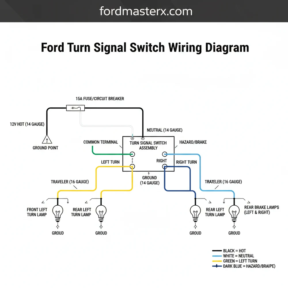
Main Components and Features of the Ford Turn Signal System
The Ford turn signal system is more than just a lever on the steering column; it is an integrated network of switches, relays, and power feeds. In most Ford models, particularly those manufactured between 1980 and 2010, the turn signal switch is part of a “Multi-Function Switch” (MFS) assembly. This assembly typically controls the left and right blinkers, the hazard lights, the high-beam headlights, and often the windshield wipers and washers.
The primary components you will encounter in a Ford wiring diagram include:
- The Multi-Function Switch (MFS): The central hub located on the steering column. It redirects power from the flasher unit to the specific set of bulbs (front and rear) based on the lever position.
- The Flasher Relay: Usually located under the dash or in the fuse panel. This component creates the rhythmic “on-off” pulse of electricity. Many Fords use a thermal flasher or an electronic relay.
- The Fuse Block: Provides protected power to the circuit. Most Fords have two separate power sources: one “hot at all times” for hazard lights and one “hot in run” for turn signals.
- The Brake Light Switch: On many Ford models, the brake light circuit passes through the turn signal switch. This allows the switch to override the brake light on one side so it can blink while the other side remains solid.
How to Read and Use a Ford Turn Signal Wiring Diagram

Reading a Ford wiring diagram requires an understanding of Ford’s specific nomenclature and color-coding standards. Unlike some manufacturers that use solid colors, Ford frequently uses “tracer” colors—a base color with a thin stripe of a different color. For example, “LG/WH” signifies a Light Green wire with a White stripe.
To read the diagram effectively, follow the path of electricity from the source to the ground. In a standard Ford turn signal circuit, the path generally looks like this:
- Power Input: Look for a wire (often Light Blue or White/Red) coming from the fuse box to the flasher relay.
- Flasher to Switch: The pulsed power leaves the flasher and enters the turn signal switch (often via a Light Blue or Purple wire).
- Distribution: Once the lever is moved, the switch sends that pulsed power to the individual corners of the vehicle.
Common Ford Turn Signal Wire Colors:
While colors can vary by decade, these are the standard “classic” and “late-model” Ford color assignments you will likely see in your diagram:
- Left Front Signal: Light Green with White stripe (LG/WH).
- Right Front Signal: White with Light Blue stripe (WH/LB).
- Left Rear Signal/Brake: Light Green with Orange stripe (LG/OG).
- Right Rear Signal/Brake: Orange with Light Blue stripe (OG/LB).
- Power Feed from Flasher: Light Blue (LB).
- Brake Light Input: Light Green (LG).
Measurements are also crucial when using the diagram for testing. Most turn signal circuits operate on a standard 12-volt DC system. When the switch is activated, you should see a fluctuating voltage (between 0V and 12V) at the output pins. If you see a steady 12V but no blinking, the flasher is likely stuck. If you see 0V, there is an open circuit or a blown fuse.
Practical Tips for DIY Enthusiasts
When you are ready to apply the wiring diagram to a physical repair, preparation is key. Use the following tips to ensure a smooth process:
1. Verify the Ground: In Ford lighting systems, a significant number of “switch failures” are actually bad grounds. The wiring diagram will show ground points (often labeled as G101, G202, etc.). These are physical bolts where the wire attaches to the chassis. If the turn signals act erratically—such as the dash lights dimming when you signal—check the ground wire near the radiator support or the rear trunk area.
2. Use a Digital Multimeter (DMM): While a test light is good for checking for the presence of power, a DMM allows you to check for “voltage drop.” If your diagram shows a wire should have 12V but your meter reads only 9V, you have high resistance (usually due to corrosion) in a connector or a frayed wire.
3. Pin Drag Testing: If you are replacing the switch because the connector looks melted, don’t just plug in the new one. Check the “tension” of the female terminals in the harness. If the metal pins have spread apart, they will create heat and melt your brand-new switch. You can gently tighten them with a small pick tool.
Troubleshooting Common Ford Turn Signal Issues
Using the wiring diagram as your roadmap, you can systematically troubleshoot the most common Ford signal failures:
The “Fast Flash” or Hyper-Flashing
Usually, this indicates a burnt-out bulb. According to the diagram, the turn signal circuit is designed with a specific load in mind. When a bulb fails, the resistance changes, causing the flasher relay to cycle faster. If all bulbs are good but it still hyper-flashes, you may have installed LED bulbs without a load resistor, or the multi-function switch has internal high resistance.
One Side Works, the Other Doesn’t
Consult your diagram to find where the circuit splits. Since the flasher and the main power feed are shared, the problem must lie within the switch itself or the wiring leading from the switch to the non-working side. Check the LG/WH wire for the left side or the WH/LB wire for the right side at the switch connector. If power is leaving the switch but not reaching the bulb, the break is in the wiring harness.
Brake Lights Work, but Turn Signals Don’t (or Vice-Versa)
This is a classic Ford issue involving the “Brake-Through-Turn” logic. On many Fords, the brake signal enters the turn signal switch on a Light Green wire. Inside the switch, it is routed to the rear LG/OG and OG/LB wires. If your brake lights work but your turn signals don’t, the issue is likely the flasher or the turn signal power feed. If turn signals work but brake lights don’t, the problem is likely the brake light switch at the pedal or the connection where it enters the multi-function switch.
The Hazards Work, but Turn Signals Don’t
This is a vital clue. Hazards and turn signals often use the same bulbs and wires to the corners, but they use different power sources and different flashers (on older Fords). If hazards work, you know the wiring to the bulbs is intact. The fault must be in the “Turn Signal” specific fuse, the turn signal flasher, or the ignition-switched power feed to the MFS.
Conclusion
Understanding the Ford turn signal switch wiring diagram is an empowering skill for any DIYer. By breaking the system down into its basic inputs (power and brake signal) and outputs (front and rear bulbs), you can move from “guessing” to “diagnosing.” Remember to always start with the simplest solutions—fuses and bulbs—before moving to the more complex multi-function switch. With a quality diagram, a reliable multimeter, and a bit of patience, you can ensure your Ford remains safe and communicative on the road for years to come.
Step-by-Step Guide to Understanding the Ford Turn Signal Switch Wiring Diagram: Easy Setup Guide
Identify the specific wire colors using the Ford turn signal switch wiring diagram.
Locate the main power source, often referred to as the hot wire, coming from the flasher.
Understand how the common terminal distributes current to the left or right traveler wire.
Connect the replacement switch to the harness, ensuring the ground wire is securely seated.
Verify that both front and rear signals flash correctly by cycling the lever.
Complete the installation by reassembling the steering column shroud and testing the hazard lights.
Frequently Asked Questions
Where is the Ford turn signal switch located?
It is inside the steering column, directly behind the steering wheel. To access it, you usually need to remove the plastic shroud surrounding the column. In many Ford models, it is integrated into a multi-function lever that also controls the wipers and high beams for the driver.
What does a Ford turn signal switch wiring diagram show?
The diagram displays the electrical paths from the fuse box to the turn signal switch and out to the exterior bulbs. It identifies the common terminal for power input and the specific traveler wire outputs for the left and right turn lamps, including the hazard light circuitry.
How many wires does a Ford turn signal switch have?
Most Ford multi-function switches utilize between 8 and 12 wires depending on the vehicle’s features. These typically include the hot wire for power, connections for front and rear signals, brake light overrides, and a ground wire to complete the circuit for internal illumination or various electronic sensors.
What are the symptoms of a bad Ford turn signal switch?
Common signs include turn signals that won’t blink, hazard lights failing to activate, or the lever not clicking into place. You might also notice that the brake lights only work when the signal is off, suggesting a short or break in the internal common terminal or wiring.
Can I install or replace this myself?
Yes, replacing this switch is a common DIY task. After disconnecting the battery, you remove the steering column trim. Most switches are held by two screws and a modular plug. Using a wiring diagram ensures you don’t confuse the neutral wire equivalents or power leads during the swap.
What tools do I need for this task?
You will need a basic socket set or screwdrivers to remove the column covers. A digital multimeter is essential for testing the hot wire and ground wire continuity, while a small pick tool helps release any stubborn plastic electrical connectors without causing damage to the sensitive vehicle harness.


